Toroidal-type continuously variable transmission
a transmission and continuous variable technology, applied in the direction of friction gearings, belts/chains/gearrings, friction gearings, etc., can solve the problems of increasing not only the weight of the surface, but also the cost, and shortening the fatigue life of these rolling surfaces and raceway surfaces. , to achieve the effect of enhancing the bending rigidity of the trunnion, facilitating work, and reducing the risk of trunnion deformation
- Summary
- Abstract
- Description
- Claims
- Application Information
AI Technical Summary
Benefits of technology
Problems solved by technology
Method used
Image
Examples
first embodiment
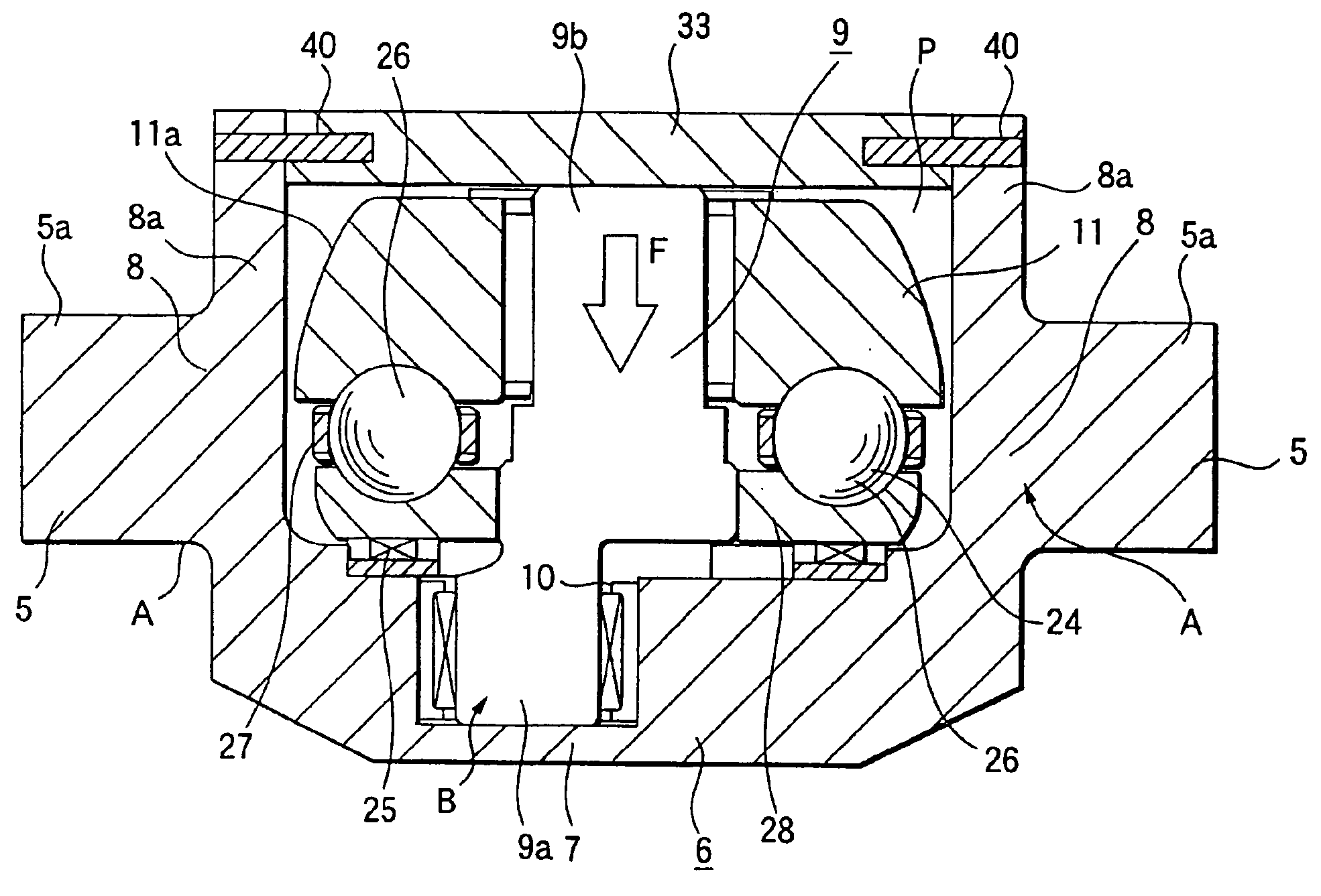
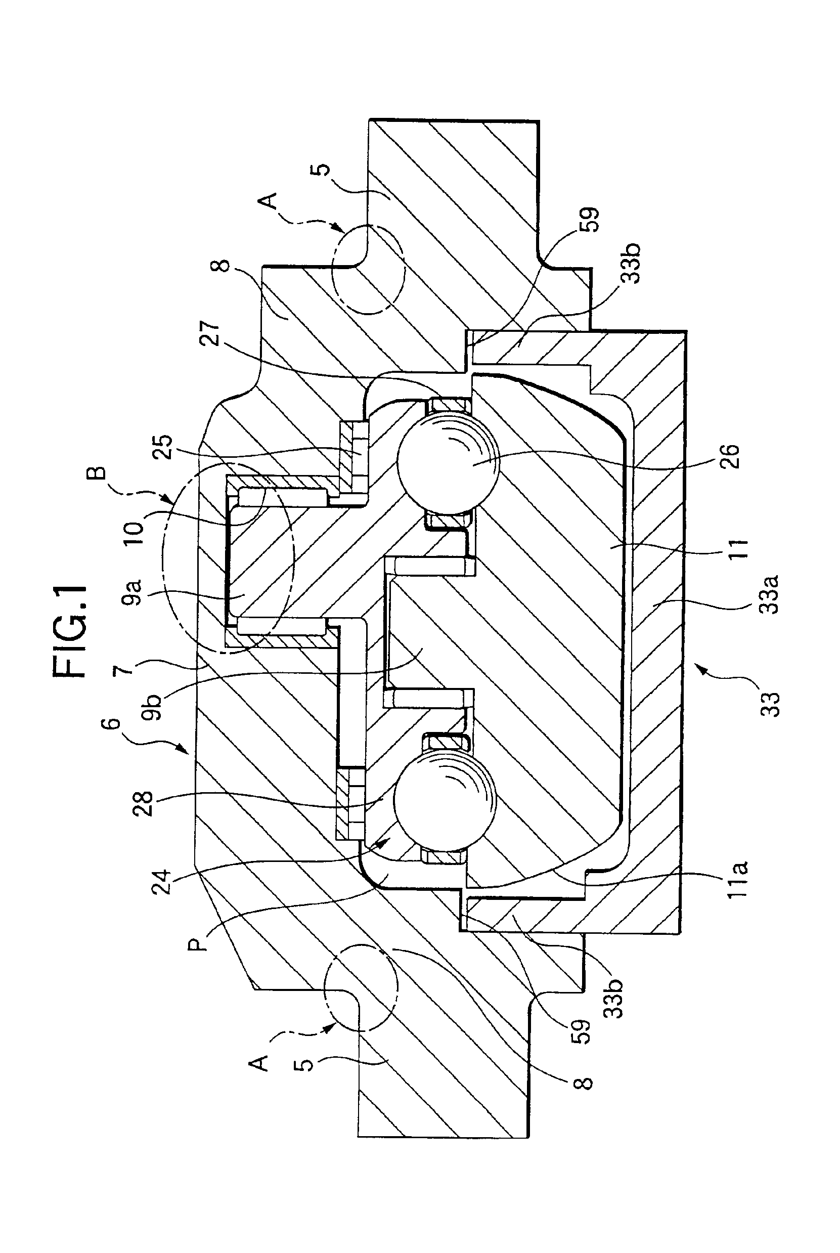
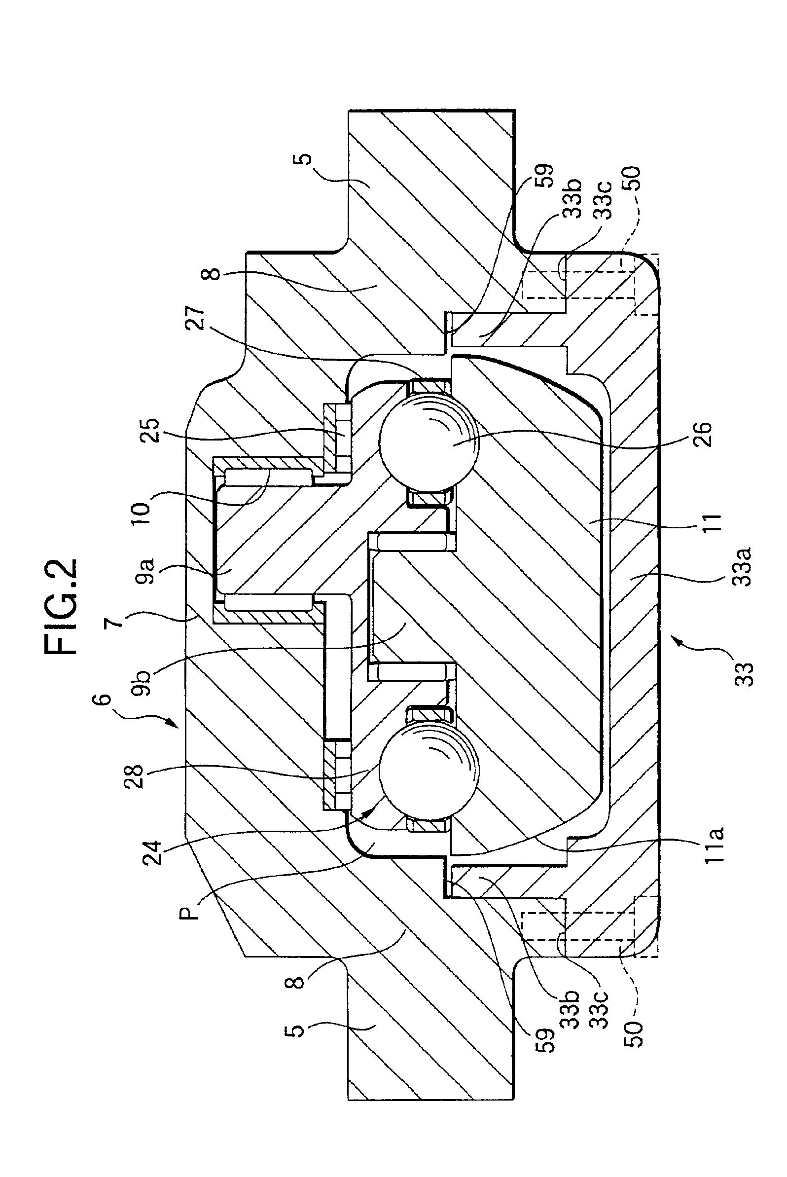
[0095]Now, FIG. 1 shows a toroidal-type continuously variable transmission according to the invention. As shown in FIG. 1, a trunnion 6 constituting a toroidal-type continuously variable transmission according to the invention, similarly to the trunnion 6 used in the previously described conventional toroidal-type continuously variable transmission, includes, on the two end portions thereof in the longitudinal direction (in FIG. 1, in the right and left direction) of the support plate portion 7, a pair of bent wall portions 8, 8 formed such that they are bent toward the inner surface side (in FIG. 1, the upper side) of the support plate portion 7. And, on the outer surfaces of the bent wall portions 8, 8, there are disposed pivot shafts 5, 5 in such a manner that they are concentric with each other.
[0096]Also, in the present embodiment, the base end portion 9a of the displacement shaft 9 and outer race 28 according to the conventional structure are formed as an integral body, and th...
sixth embodiment
[0122]Now, FIG. 8 shows a toroidal-type continuously variable transmission according to the invention. As shown in FIG. 8, a trunnion 6 constituting a toroidal-type continuously variable transmission according to the present embodiment, similarly to the trunnion 6 used in the previously described conventional toroidal-type continuously variable transmission, includes, on the two end portions thereof in the longitudinal direction (in FIG. 8, in the right and left direction) of the support plate portion 7, a pair of bent wall portions 8, 8 which are formed so as to be bent toward the inner surface side (in FIG. 8, the upper side) of the support plate portion 7. And, on the outer surfaces of the bent wall portions 8, 8, there are disposed pivot shafts 5, 5 in such a manner that they are concentric with each other.
[0123]The trunnion 6 has hardness of HRC45 or lower through heat treatment for refining. Also, the transfer surface portions 5a of a radial needle roller bearing 32 for suppor...
seventh embodiment
[0152]Now, FIGS. 15 to 17 show a toroidal-type continuously variable transmission according to the invention. As shown in FIG. 15, to the inner surface of a housing 38, there is fixed a support post 34 which is used to support the middle portions of support plates (yokes) 23 for supporting their respective trunnions 6 in such a manner that the present middle portions can be swung as well as can be shifted in the axial direction (in FIG. 15, in the right and left direction) of their associated pivot shafts 5, 5. And, a hold metal member 36 is connected and fixed by a connecting screw 37 to the central portion of the leading end portion of the support post 34 that is situated on the inner surface side of the support plates 23. In the leading end portion of the hold metal member 36, there is formed a flange-shaped hold portion 39 the outside diameter of which is larger than that of the near-to-base-end portion of the hold metal member 36.
[0153]Also, the connecting screw 37 penetrates t...
PUM
 Abstract
Description
Claims
Application Information
 - R&D Engineer
- R&D Manager
- IP Professional
- Industry Leading Data Capabilities
- Powerful AI technology
- Patent DNA Extraction
Browse by: Latest US Patents, China's latest patents, Technical Efficacy Thesaurus, Application Domain, Technology Topic, Popular Technical Reports.
© 2024 PatSnap. All rights reserved.Legal|Privacy policy|Modern Slavery Act Transparency Statement|Sitemap|About US| Contact US: help@patsnap.com


