Filter in a filter housing

Inactive Publication Date: 2006-02-28
MANN HUMMEL GMBH
View PDF11 Cites 179 Cited by
  • Summary
  • Abstract
  • Description
  • Claims
  • Application Information

AI Technical Summary

Benefits of technology

[0009]In the filter according to this invention, the housing cover sits in an area of the filter housing between the oncoming flow side and the outgoing flow side of the filter element and is situated outside the flow path of the liquid or gaseous fluid to be purified. Thus the housing cover does not constitute an obstacle for the fluid to be purified, so the filter can be integrated into the line system in such a way that the connections between the line segments for supplying and/or carrying away of fluid in the area of the oncoming flow side and the outgoing flow side together with the filter element form a continuous flow path that is free of obstacles. Unwanted fluid stagnation spaces can be avoided. In addition, the filter can be installed axially in the flow path in a simple design.
[0010]For maintenance purposes, it is sufficient to open the housing cover so that the receptacle chamber in the filter housing is made accessible and the soiled filter element can be replaced with an unused filter element without requiring dismantling of the filter from its installed position in the line system. The unfiltered air lines and clean air lines need not be removed to replace the filter element. This greatly simplifies maintenance work.
[0011]Another advantage is that in particular the connections in the oncoming flow area and in the outgoing flow area of t

Problems solved by technology

This embodiment has the disadvantage that the housing cover in the oncoming flow area must be removed to replace the filter element, which initially requires dismantling of the entire filter housing from its installed position, because th

Method used


Image

  • Filter in a filter housing
  • Filter in a filter housing
  • Filter in a filter housing

Examples


Embodiment Construction

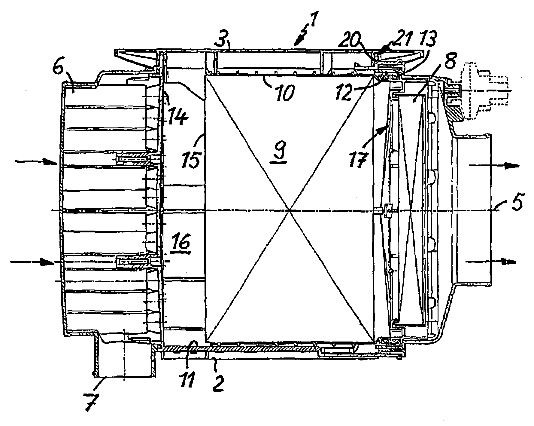
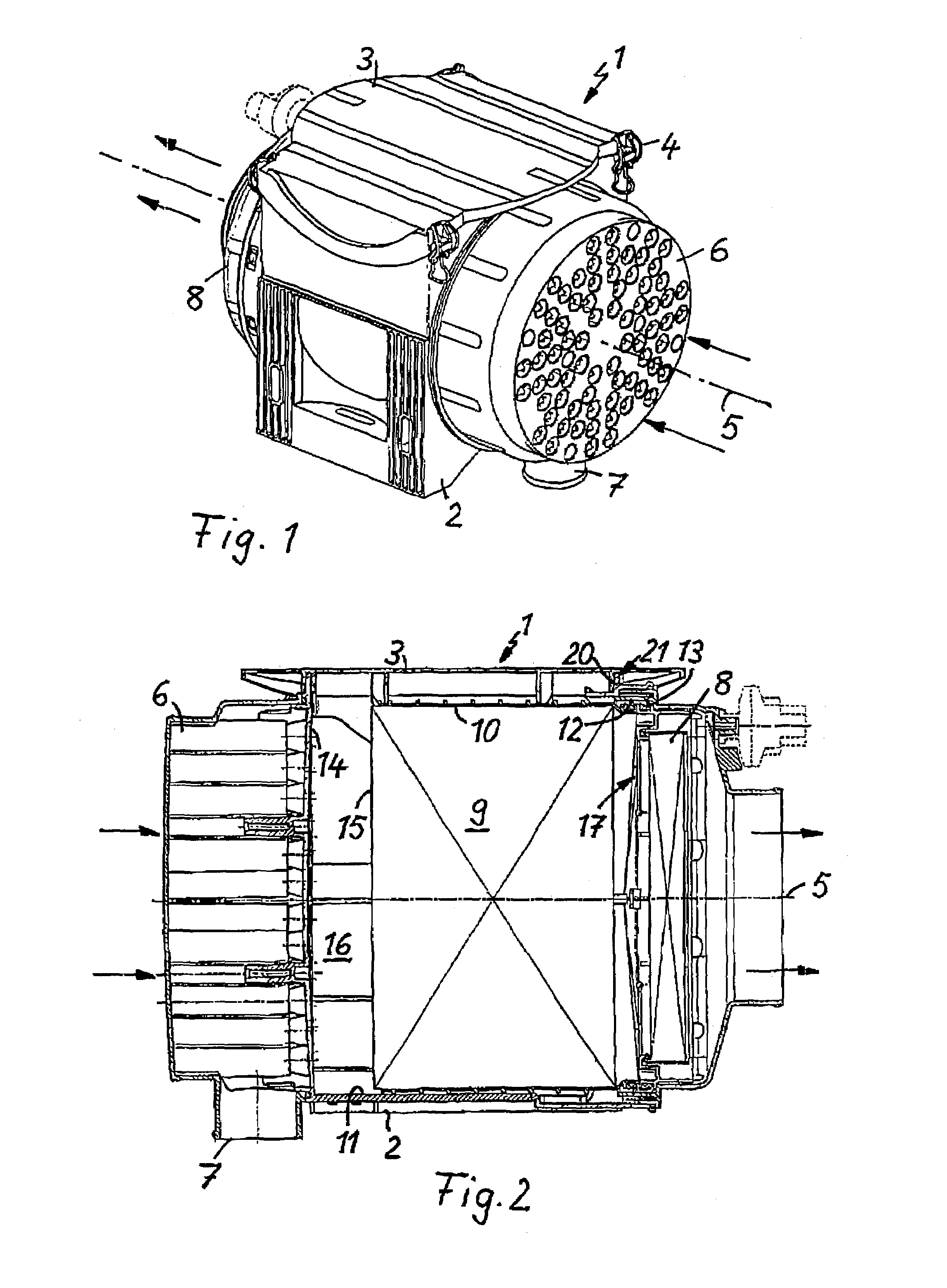
[0027]Filter 1, shown in FIG. 1, comprises in particular an air filter, which is situated in the intake tract of an internal combustion engine and is connected upstream from the air intakes of the engine for purification of the combustion air. Filter 1 has a filter housing 2 in which the filter element is accommodated and a housing cover 3 with which a receptacle chamber for accommodating the filter element is to be sealed. Housing cover 3 is to be fixedly locked to filter housing 2 by locking elements 4. The filter element is designed to be approximately cylindrical with the flow passing through it axially in the direction of longitudinal axis 5 according to the arrows shown. The unfiltered air to be purified is sent to filter 1 axially on its oncoming flow side while the purified clean air also leaves the filter axially through its outgoing flow side.

[0028]A prefilter designed as a cyclone pre-separator 6 is connected upstream from the central filter element accommodated in the fi...


PUM

PropertyMeasurementUnit
Areaaaaaaaaaaa
Distanceaaaaaaaaaa

Abstract

A filter has a filter housing and a receptacle chamber in the filter housing into which a filter element is insertable. The filter housing has a housing cover for opening and closing an opening of the receptacle chamber. The housing cover is situated in an area of the filter housing between the oncoming flow side and the outgoing flow side of the filter element.

Description

BACKGROUND OF THE INVENTION[0001]This invention relates to a filter comprising a filter housing defining a filter receptacle chamber and a housing cover for opening and / or closing the receptacle chamber, and a filter element which is insertable into and removable from the receptacle chamber in the filter housing.[0002]U.S. Pat. No. 6,322,602 B2 describes an air filter having a filter element, which is to have axial flow through it, in a cylindrical filter housing. The receptacle chamber for accommodating the filter in the filter housing is to be sealed on an axial end face in the area of the oncoming flow side of the filter by a housing cover which is loosened to replace the filter element, whereupon the filter element can be removed from the receptacle chamber and replaced by a new filter element.[0003]This embodiment has the disadvantage that the housing cover in the oncoming flow area must be removed to replace the filter element, which initially requires dismantling of the entir...

Claims


Application Information

Patent Timeline
IPC IPC(8): B01D46/00B01D46/24B01D46/42B01D50/00
CPCB01D46/0004B01D50/002B01D46/525B01D50/20B01D46/4227
Inventor KOPEC, EDVARDWINTER, MANFREDGREIF, VOLKERDWORATZEK, KLEMENSHARTMANN, MARIONMUENKEL, KARLHEINZHAEHN, JENSSTINZENDOERFER, JOACHIM
Owner MANN HUMMEL GMBH
Why Eureka
Try Eureka