
Tapered piezoelectric in-plane bimorph and method of fabricating

a piezoelectric and in-plane bimorph technology, applied in piezoelectric/electrostrictive/magnetostrictive devices, piezoelectric/electrostriction/magnetostriction machines, electrical equipment, etc., can solve the problem of large-scale motors that lack the resolution to effectively accommodate high-density discs, large activation voltages, and difficulty in fabrication

Inactive Publication Date: 2006-02-28
SEAGATE TECH LLC
View PDF7 Cites 9 Cited by
  • Summary
  • Abstract
  • Description
  • Claims
  • Application Information

AI Technical Summary

Problems solved by technology

The large-scale motor lacks sufficient resolution to effectively accommodate high track-density discs.
The existing problems in the prior art schemes for a high resolution microactuator include difficulties in fabrication, large activation voltages required for deforming materials a sufficient amount to control the transducer position, lack of fast response bandwidth required in disc operation, and simplicity of implementation.
The tapered design, however, also presents challenges in dicing operation during fabrication of the piezoelectric microactuators due to their two non-parallel sides.

Method used


Image

  • Tapered piezoelectric in-plane bimorph and method of fabricating
  • Tapered piezoelectric in-plane bimorph and method of fabricating
  • Tapered piezoelectric in-plane bimorph and method of fabricating

Examples


Embodiment Construction

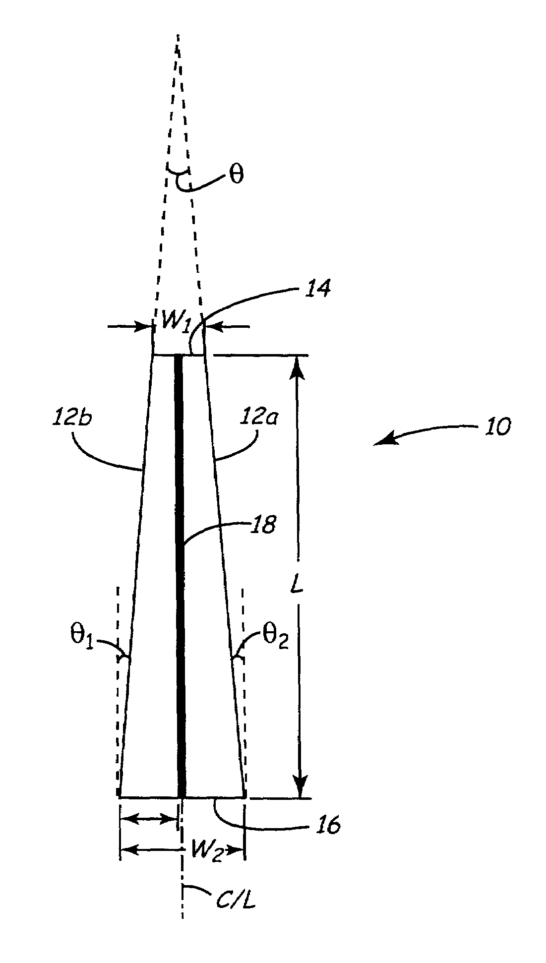
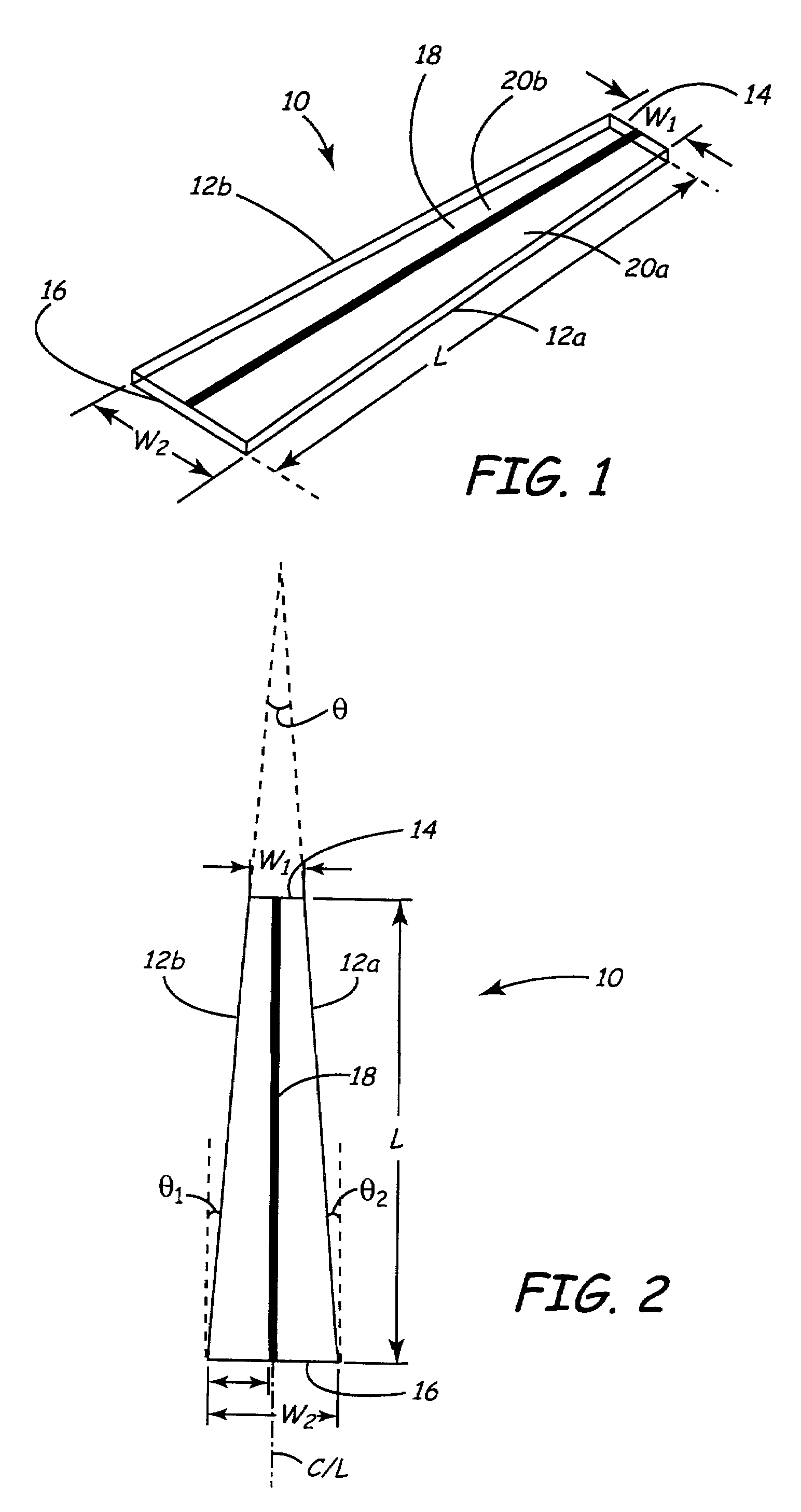
[0027]The present invention involves a method of efficiently fabricating tapered elements from a substrate having a size many times that of a single element. In the present application, the term element and elements are used to represent a single piece or pieces of a material formed as a result of cutting a larger substrate. Such piece or pieces are often called “die” or “dice”. Unless specified otherwise, the term elements or element does not suggest a particular geometric shape thereof or a particular cutting method used to cut the substrate. The substrate may be either a wafer or a smaller piece of a wafer resulted from cutting the wafer (e.g., a wafer bar cut from a wafer).

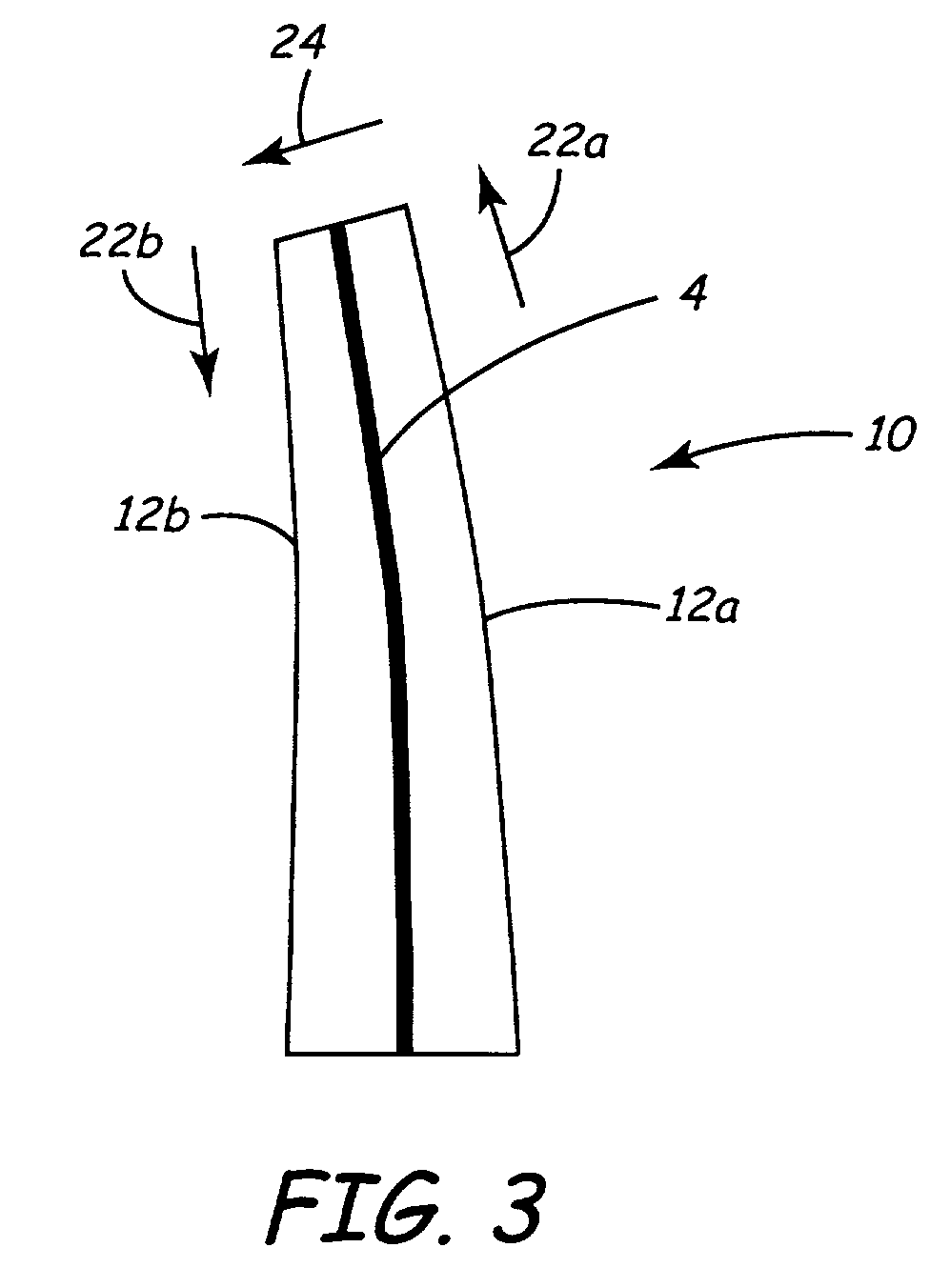
[0028]The elements are used, or further adapted to be used, as devices such as transducers or microactuators. In the present disclosure, the method is illustrated using a process for making in-plane piezoelectric bimorph elements from a piezoelectric substrate. The resultant piezoelectric bimorph elements are ...


PUM

PropertyMeasurementUnit
feature angleaaaaaaaaaa
sizeaaaaaaaaaa
distanceaaaaaaaaaa

Abstract

Tapered elements fabricated from a substrate of a size many times that of a single element are disclosed. Such tapered elements may be used as piezoelectric microactuators such as in-plane piezoelectric bimorph microactuators. A unique method of fabricating such tapered elements is provided. According to the method, cutting directions are first defined, the substrate is then cut a plurality of times in each cutting direction with adjacent cuts in each cutting direction indexed by proper indexing distances which are determined based on the dimensions of the final tapered elements. In one embodiment of the method, a plurality of optically detectable marks are used to define the cutting directions and cutting means is accordingly optically aligned with the cutting directions.

Description

CROSS-REFERENCE TO RELATED APPLICATION(S)[0001]This application claims priority from Provisional Application No. 60 / 260,755 filed Jan. 10, 2001 for “Fabricating Tapered Piezoelectric In-plane Bimorph” by John S. Wright and James M. Murphy.BACKGROUND OF THE INVENTION[0002]The present invention relates to fabricating elements or devices from a substrate having a size many times greater than that of a single element. More particularly, the present invention relates to tapered piezoelectric in-plane bimorphs and method of fabricating such bimorphs from a substrate of a size many times that of a single bimorph, wherein each bimorph has two angled opposing sides, a top having a top width, and a bottom having a bottom width which is greater than the top width.[0003]As the areal density of concentric data tracks on magnetic discs continues to increase (that is, the size of data tracks and radial spacing between data tracks are decreasing), more precise head positioning is required. Head pos...

Claims


Application Information

Patent Timeline
Patent Type & Authority Patents(United States)
IPC IPC(8): H01L41/08H10N30/00H01L41/24H10N30/20
CPCH01L41/094H01L41/338Y10T29/42H10N30/2045H10N30/088
Inventor WRIGHT, JOHN STUARTMURPHY, JAMES MORGAN
Owner SEAGATE TECH LLC
Learn More