Circuit and method for impedance detection

a technology of impedance detection and circuit, applied in the field of circuit and method, can solve the problems of increasing error and increasing detection error, and achieve the effect of enhancing input impedan

Inactive Publication Date: 2006-02-28
TOKYO ELECTRON LTD
View PDF13 Cites 12 Cited by
  • Summary
  • Abstract
  • Description
  • Claims
  • Application Information

AI Technical Summary

Benefits of technology

[0017]Also, the impedance converter may be made up of a voltage follower, or a voltage amplifier of which voltage gain is less than or more than 1. Then, when an input side of the impedance converter is made up of a circuit comprising MOSFET, the input impedance may further be enhanced.

Problems solved by technology

However, when very small capacitance, which equals to or is less than an order of several pF or fF (femtofarad), is detected, an error is increased.
Also, depending on a frequency of the AC voltage Vac applied, a subtle displacement of a phase and amplitude consequently arises between the voltage of the inverting input terminal and that of the non-inverting input terminal, which are in the imaginary short status, due to a tracking error in the operational amplifier 59, and thereby the detection error becomes bigger.

Method used


Image

  • Circuit and method for impedance detection
  • Circuit and method for impedance detection
  • Circuit and method for impedance detection

Examples


first embodiment

(First Embodiment)

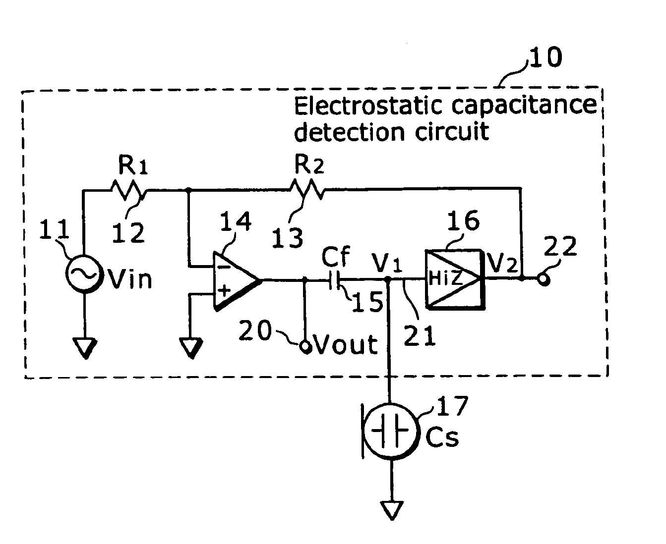
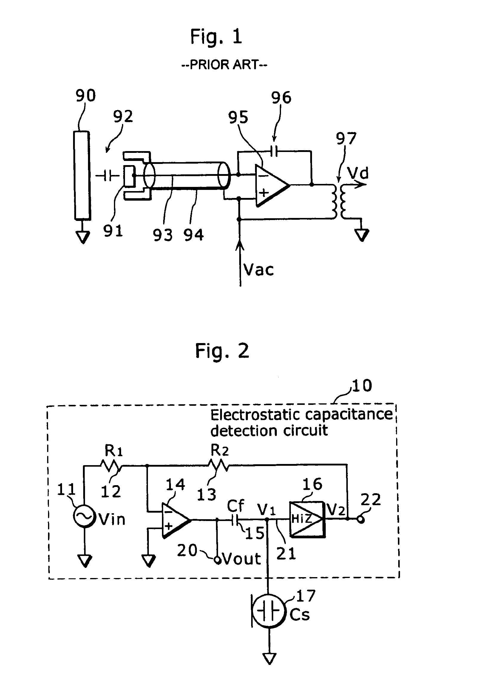
[0034]FIG. 2 is a circuit diagram of an impedance detection circuit according to a first embodiment of the present invention. In this diagram, a capacitor to be detected 17 (i.e. a capacitance type sensor that detects various types of physical quantities using a fluctuation in the electrostatic capacitance Cs such as a capacitor microphone in this example.), which is a subject for detection as an impedance to be detected, is connected to an electrostatic capacitance detection circuit 10 as the impedance detection circuit.

[0035]This electrostatic capacitance detection circuit 10 comprises an DC voltage generator 11 that generates AC voltage, a resistance (R1) 12, a resistance (R2) 13, an operational amplifier 14, an impedance element 15 (a capacitor with capacitance Cf in this example) and an impedance converter 16, and outputs a detection signal (voltage V out) corresponding to a temporal change in electrostatic capacitance of the capacitor 17 from a signal output ...

second embodiment

(Second Embodiment)

[0067]Next, the following describes an impedance detection circuit according to a second embodiment of the present invention.

[0068]FIG. 4 is a circuit diagram of an electrostatic capacitance detection circuit 40 as the impedance detection circuit according to the second embodiment of the present invention. This electrostatic capacitance detection circuit 40 is equivalent to what a guarding function is added to the electrostatic capacitance detection circuit 10 according to the first embodiment. That is, as a cable to connect the capacitor 17 with the electrostatic capacitance detection circuit 40, a signal line 41 (a coaxial cable) covered with a shielding line 42 is used, and additionally a guard voltage applying circuit 43a for applying guard voltage, of which potential is the same as that of the signal line 41, is added to the shielding line 42 of the coaxial cable.

[0069]By making the guard voltage applying circuit 43a be connected between the output terminal o...


PUM

PropertyMeasurementUnit
electrostatic capacitanceaaaaaaaaaa
impedanceaaaaaaaaaa

Abstract

An electrostatic capacitance detection circuit 10 comprises a DC voltage generator 11, an operational amplifier 14 of which non-inverting input terminal is connected to specific potential, an impedance converter 16, a resistance (R1) 12 connected between the DC voltage generator 11 and an inverting input terminal of the operational amplifier 14, a resistance (R2) 13 connected between the inverting input terminal of the operational amplifier 14 and an output terminal of the impedance converter 16, and a capacitor 15 connected between an output terminal of the operational amplifier 14 and an input terminal of the impedance converter 16. A capacitor to be detected 17 is connected between the input terminal of the impedance converter 16 and specific potential.

Description

TECHNICAL FIELD[0001]The present invention relates to a circuit and a method that detect impedance and electrostatic capacitance, especially relates to the circuit and the method that detect very small impedance and capacitance with high accuracy.BACKGROUND ART[0002]As a prior art of an electrostatic capacitance detection circuit, that described in Japanese Laid-Open Patent Application H09-280806 gazette can be cited. FIG. 1 is a circuit diagram that shows this electrostatic capacitance detection circuit. In this detection circuit, a capacitive sensor 92 comprised of electrodes 90 and 91 is connected to an inverting input terminal of an operational amplifier 95 via a signal line 93. And a capacitor 96 is connected between an output terminal of this operational amplifier 95 and the said inverting input terminal, and further an AC voltage Vac is applied to a non-inverting input terminal. Also, the said signal line 93 is wrapped up by a shield line 94 and shielded electrically against ...

Claims


Application Information

Patent Timeline
Patent Type & Authority Patents(United States)
IPC IPC(8): G01R27/26G01N27/22H04R29/00
CPCH04R29/004G01R27/26
Inventor YAKABE, MASAMIIKEUCHI, NAOKI
Owner TOKYO ELECTRON LTD
Why Eureka
Try Eureka