
Wireless locating and tracking systems

a tracking system and wireless technology, applied in the field of wireless locating and tracking systems, can solve the problems of high setup cost, low resolution and accuracy of the type of system, and introduce errors into the system, and achieve the effect of maximum range and omni-directionality

Inactive Publication Date: 2006-02-28
SYMBOL TECH LLC
View PDF19 Cites 207 Cited by
  • Summary
  • Abstract
  • Description
  • Claims
  • Application Information

AI Technical Summary

Benefits of technology

The present invention provides methods and apparatus for locating and tracking assets that are associated with RFID / RFDC devices and RF tags at known locations. The RFID / RFDC devices interrogate the RF tags and receive response signals, which can be sent to a host computer to locate and track the assets. The invention also includes an RF tag antenna design that allows for maximum range and omni-directionality by selectively connecting multiple antennas through a switching mechanism. The technical effects of the invention include improved asset location and tracking capabilities, improved range and omni-directionality, and improved RF tag antenna design.

Problems solved by technology

This type of system typically has a low level of resolution and accuracy.
Multi-path fading effects and other types of interferences also introduce errors into this type of system.
This setup tends to be costly in relatively small sites where at least three receivers need to be used and can become very expensive in large sites when more receivers need to be added.
In the past, RF tags have been used in a limited capacity to track the location of assets.
This system, however, does not provide the ability to track assets within storage facilities and does not provide total asset visibility.
This approach may be impractical due to ergonomics, space, and size constraints.
This system, however, provides a limited tracking resolution and is prone to human error.

Method used


Image

  • Wireless locating and tracking systems
  • Wireless locating and tracking systems
  • Wireless locating and tracking systems

Examples


Embodiment Construction

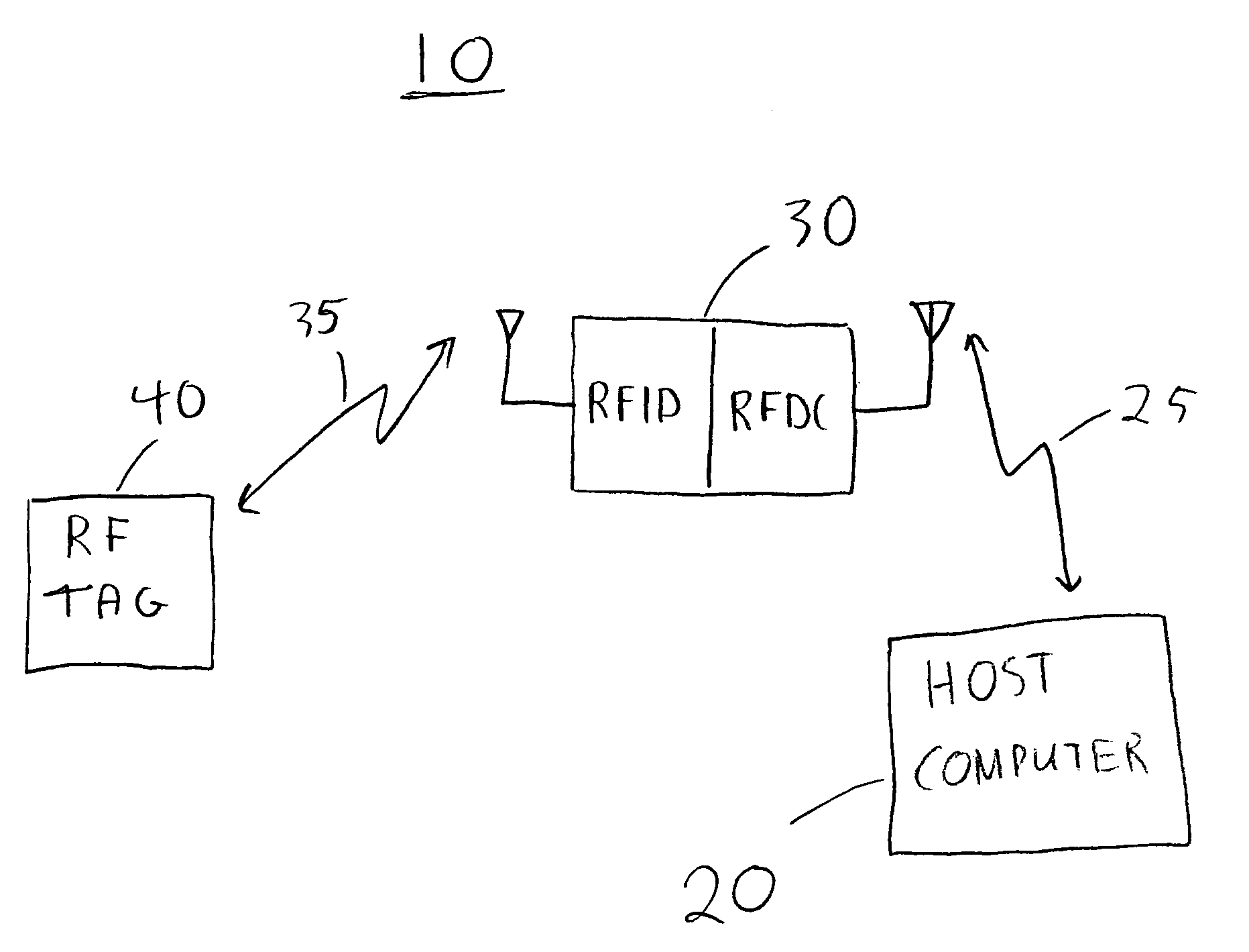
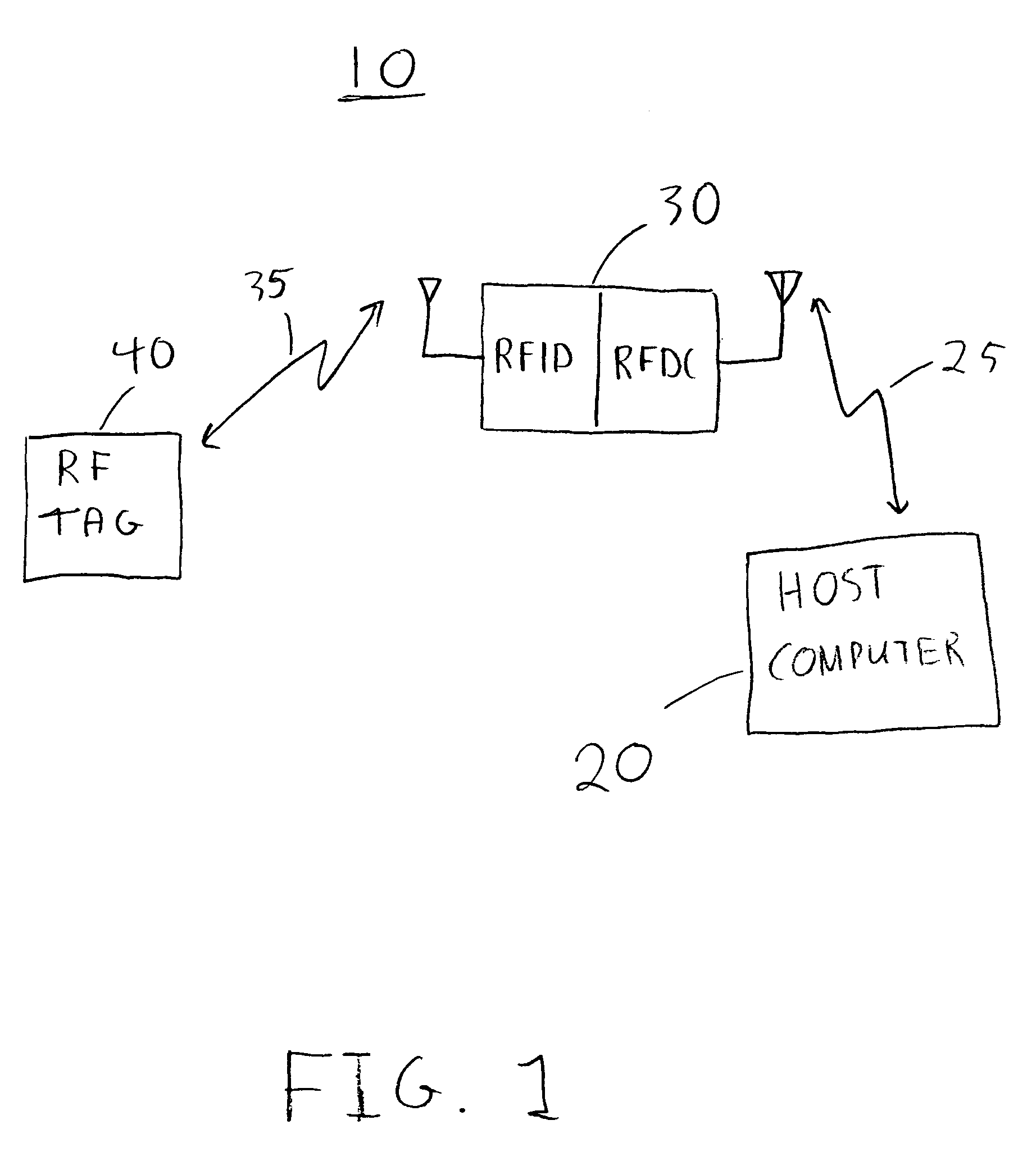
[0021]An illustrative simplified wireless locating and tracking system 10 in accordance with the present invention is shown in FIG. 1. The asset or assets desired to be located or tracked may contain either RF tag 40 or RFID / RFDC device 30. Depending on which device is attached to the asset, the other device, either the RF tag 40 or the RFID / RFDC device 30, is placed at a known location. Only one RF tag 40 and one RFID / RFDC device 30 are illustrated in FIG. 1 for clarity. It will be understood that multiple RF tags 40 and RFID / RFDC devices 30 that may be present in system 10.

[0022]RFID / RFDC device 30 contains a radio frequency identification circuit that provides signals to and receives signals from RF tag 40 via communications path 35. RFID / RFDC device 30 typically sends interrogation signals to RF tag 40. Communications path 35 is a wireless communications path which may include acoustic, optical (e.g., infra-red), radio frequency communications, a combination of these paths or an...


PUM


Abstract

A locating and tracking system is provided in which the assets desired to be located and tracked are associated with either radio frequency (RF) tags or radio frequency identification and radio frequency data communication (RFID / RFDC) devices. Depending on which device is attached to the asset, the other device is located at known locations. The RFID / RFDC devices interrogate and receive signals from the RF tags. The received information is sent to a host computer. With the location of either the RF tags or RFID / RFDC devices known, the assets may be located and tracked. An improved RF tag antenna design is also provided by using a switching mechanism connected to at least two antennas.

Description

BACKGROUND OF THE INVENTION[0001]This invention relates to wireless locating and tracking systems, and more particularly to locating and tracking physical assets or personnel, and taking inventory with radio frequency (RF) tags and radio frequency identification and radio frequency data communication (RFID / RFDC) devices.[0002]There are existing systems that locate and track assets via triangulation techniques. An exemplary system may use radio beacons attached to the assets and at least three receivers placed at known locations. By measuring the time delay in the received signals at each receiver, the asset can be mapped to a location. This type of system typically has a low level of resolution and accuracy. The resolution and accuracy depend upon the ability to measure extremely small time delays and synchronize each receiver to a common clock. Multi-path fading effects and other types of interferences also introduce errors into this type of system. This setup tends to be costly in...

Claims


Application Information

Patent Timeline
Patent Type & Authority Patents(United States)
IPC IPC(8): G01S1/00G01S13/87H04B7/26G06K17/00H01Q1/22H01Q3/24H01Q21/29
CPCG01S13/876G06K19/07767H01Q21/29H01Q1/2225H01Q3/247H01Q1/22G06K2017/0045
Inventor BRIDGELALL, RAJ
Owner SYMBOL TECH LLC
Learn More