
Fast and slow time scale clutter cancellation

a clutter cancellation and slow time technology, applied in the field of nonstationary clutter cancellation, can solve the problems of insufficient clutter rejection of current space time adaptive algorithm (stap) algorithms for clutter cancellation, inability to reliably detect or image targets of sar imaging, and failure of vhf and uhf frequency approaches in many instances, so as to eliminate said fast scale clutter

Active Publication Date: 2006-02-28
RAYTHEON CO
View PDF17 Cites 28 Cited by
  • Summary
  • Abstract
  • Description
  • Claims
  • Application Information

AI Technical Summary

Benefits of technology

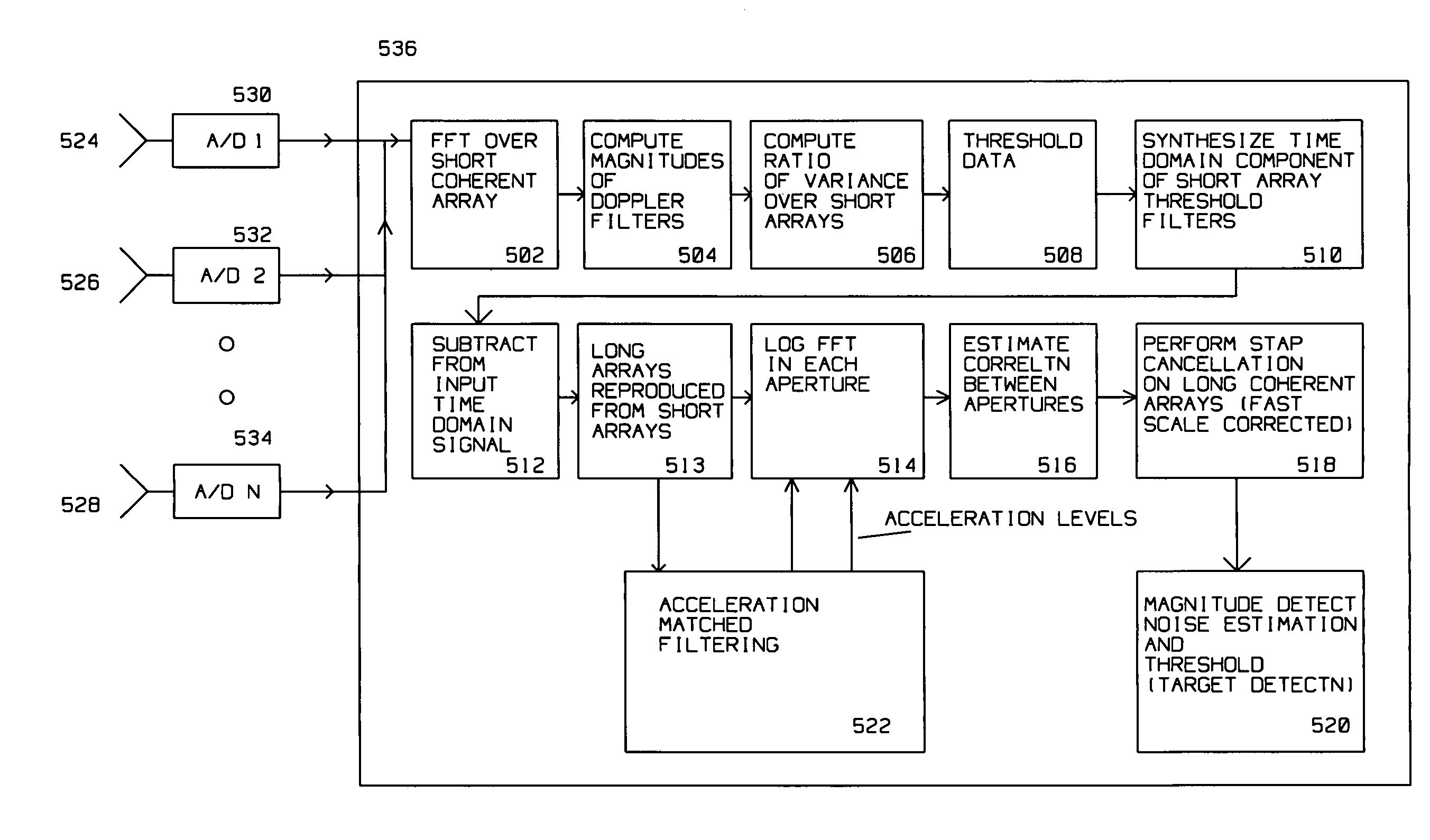
[0021]Fast scale clutter corrected data is synthesized to form said long coherent arrays to obtain fast scale corrected data thereby eliminating said fast scale clutter. A Space Time Adaptive Algorithm (STAP) is applied to compressed data extracted from the fast scale corrected data.

Problems solved by technology

However, where ground targets of interest are near a source of fast varying clutter, such as foliage on vegetation subject to turbulent wind, SAR imaging may not reliably detect or image the targets.
However, this VHF and UHF frequency approach failed in many instances because of the effect of the Doppler shift induced in the SAR imaging by slow and fast clutter coupled to the presence of noise.
Current Space Time Adaptive Algorithm (STAP) algorithms for clutter cancellation do not provide sufficient clutter rejection to allow imaging / detection in non-stationary clutter.

Method used


Image

  • Fast and slow time scale clutter cancellation
  • Fast and slow time scale clutter cancellation
  • Fast and slow time scale clutter cancellation

Examples


Embodiment Construction

[0031]The present invention describes an apparatus and method for canceling the effects of non-stationary clutter on SAR images of targets located in the proximity of foliage related clutter and / or maritime clutter from small waves and surf.

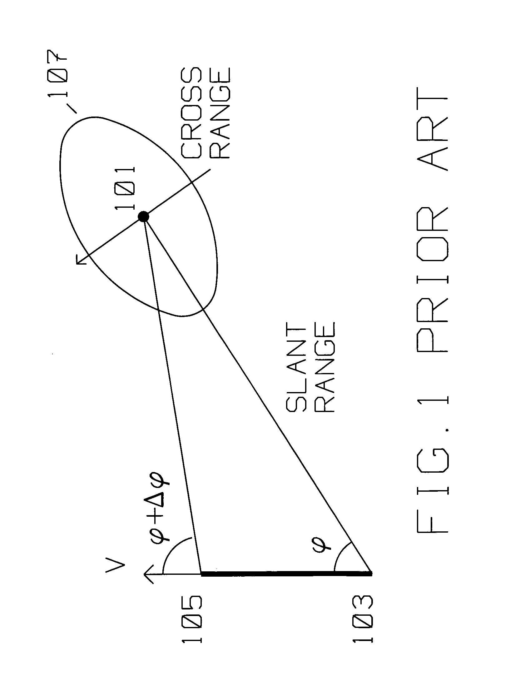
[0032]FIG. 1 shows the typical prior art geometric relationship between a moving plat- form carrying a radar transmitter / receiver using Synthetic Aperture (SAR) spotlight methods and target area 101 to be imaged by said radar transmitter / receiver. The moving platform is initially at position 103, travels with velocity V in the direction shown to position 105. In SAR spotlight mode, the SAR antenna is actively oriented towards scatterer 101 as the platform moves with respect to scatterer 101 with velocity V. The moving platform moves from position 103 to position 105, while adjusting the side looking angle from φ to φ+Δφ for spotlight mode so that the antenna keeps illuminating target area 101. Antenna illumination with radar energy covers area 10...


PUM


Abstract

Target detection in the presence of non stationary clutter is improved by a radar receiver on a moving platform for detecting a target using a plurality of short coherent arrays and a plurality of long coherent arrays synthesized from the short coherent arrays overlapping the target. The target is obscured by slow scale clutter and fast scale clutter in the vicinity of the target. The radar receiver has a plurality of subapertures overlapping to acquire radar returns reflected from the target during the arrays, an analog to digital converter for each of the subapertures to convert the radar returns into digital radar returns for a plurality of range bins covering the target, the slow scale clutter and the fast scale clutter; and a digital computer for performing steps of SAR image creation, further enhanced by thresholding short array magnitude data, computing a time domain component of threshold filters using the thresholded short array magnitude data then coherently subtracting the time domain component of threshold filters from the short arrays, and using the result to synthesize long coherent arrays. A Space Time Adaptive Algorithm (STAP) is applied to the long coherent arrays thus obtained to suppress slow and stationary clutter. The short coherent arrays are between 10 and 400 milliseconds long. The long coherent arrays are between 400 and 4000 milliseconds long.

Description

BACKGROUND OF THE INVENTION[0001]1. Field of the Invention[0002]This invention is in the field of non-stationary clutter cancellation for use with radar imaging and / or target detection.[0003]2. Description of the Related Art[0004]Synthetic Aperture Radar (SAR) radar is used for ground mapping as well as target identification. The general principle behind SAR is to coherently combine the amplitude and phase information of radar returns from a plurality of sequentially transmitted pulses from a relatively small antenna on a moving platform.[0005]The plurality of returns creating a SAR image generated by the transmitted pulses along a known path of the platform make up an array. During the array, amplitude as well as phase information returned from each of the pulses, for each of many range bins, is preserved. The SAR image is formed from the coherent combination of the amplitude and phase of return(s) within each range bin, motion compensated for spatial displacement of the moving pla...

Claims


Application Information

Patent Timeline
IPC IPC(8): G01S7/292G01S13/00G01S13/90
CPCG01S13/9029G01S13/887
Inventor KRIKORIAN, KAPRIEL V.ROSEN, ROBERT A.KRIKORIAN, MARY
Owner RAYTHEON CO
Learn More