Control system and method for an equipment service vehicle
Inactive Publication Date: 2006-02-28
OSHKOSH CORPORATION
View PDF167 Cites 154 Cited by
Summary
Abstract
Description
Claims
Application Information
AI Technical Summary
This helps you quickly interpret patents by identifying the three key elements:
Problems solved by technology
Method used
Benefits of technology
[0006]According to a preferred embodiment, an airport rescue fire fighting vehicle comprises a turret system and a control system. The turret system further comprises an articulated boom assembly, a nozzle, and a penetrating probe. The nozzle and the penetrating probe are mounted at an end of the boom assembly. The penetrating probe is configured to penetrate a skin of an aircraft. The control system further comprises a plurality of input devices, a plurality of output devices, and a plurality of interface modules. The input and
Problems solved by technology
Due to the significant number of I/O devices on-board an ARFF vehicle, performing vehicle wiring of an ARFF vehicle has been a time consuming task.
For example, to connect wiring from I/O devices in the cab area, it has generally not been possible to perform bench top w
Method used
Image
Click on the blue label to locate the original text in one second.
Reading with bidirectional positioning of images and text.
Examples
Embodiment Construction
[0025]Patent application Ser. No. 09 / 384,393, filed Aug. 27, 1999, now U.S. Pat. No. 6,421,593 and the other patent applications mentioned above disclose various embodiments of a control system architecture in connection with various types of equipment service vehicles including airport rescue and fire fighting vehicles. For convenience, portions of the above-mentioned applications are repeated below, followed by a description of preferred embodiments of an airport rescue and fire fighting vehicle and related manufacturing techniques.
A. Fire Truck Control System
[0026]1. Architecture of Fire Truck Control System
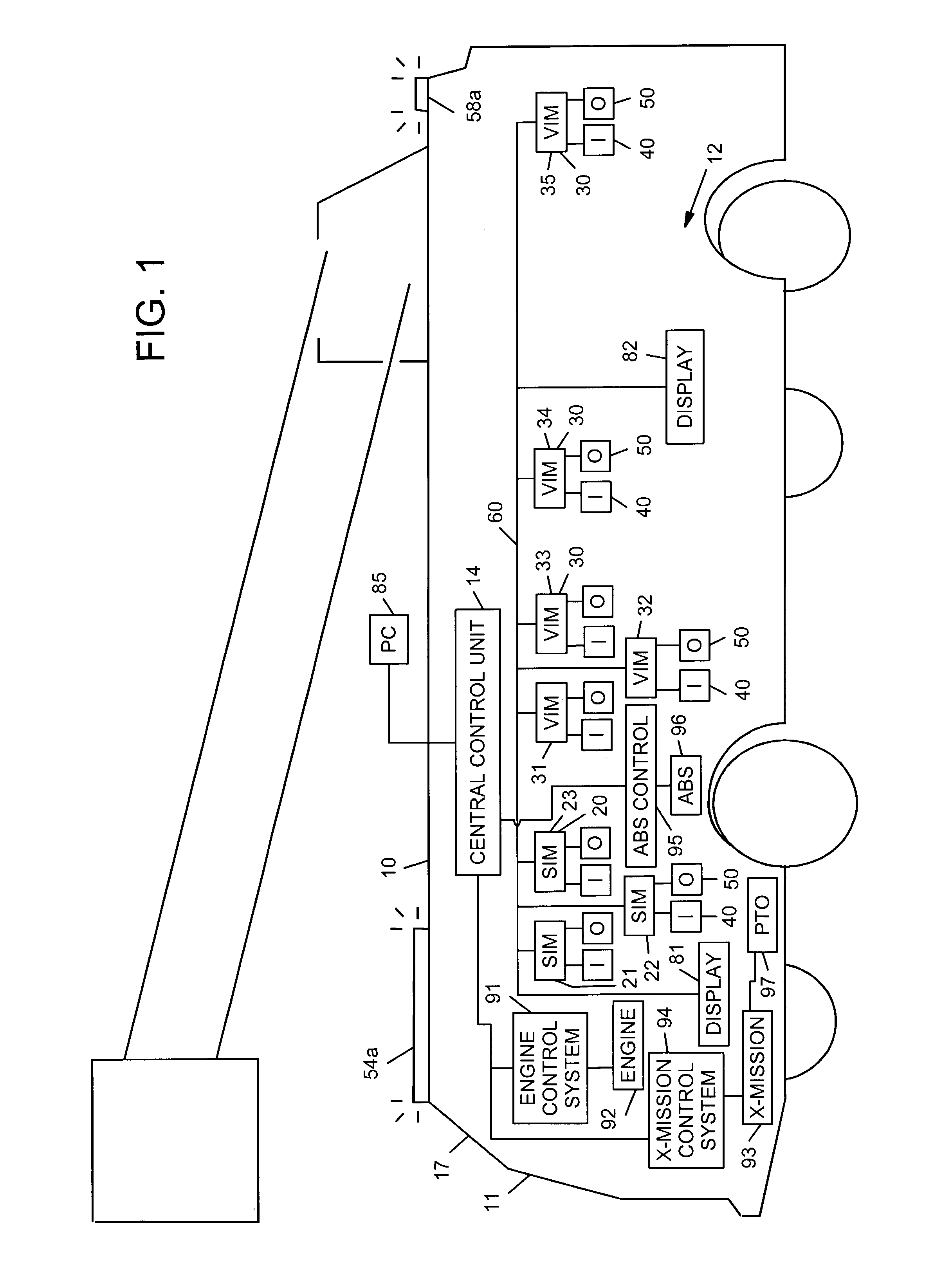
[0027]Referring now to FIG. 1, a fire truck 10 having a control system 12 is illustrated. By way of overview, the control system 12 comprises a central control unit 14, a plurality of microprocessor-based interface modules 20 and 30, a plurality of input devices 40 and a plurality of output devices 50. The central control unit 14 and the interface modules 20 and 30 are connect...
PUM
Abstract
An aircraft rescue fire fighting vehicle comprises a chassis module, a cab module, and a control system. The control system further comprises a plurality of input devices, a plurality of output devices, a plurality of interface modules, and a communication network. The plurality of interface modules is distributed throughout the fire fighting vehicle and are coupled to each other by way of the communication network. The plurality of interface modules are each coupled to the plurality of input devices and output devices. The plurality of interface modules are operative to control the output devices based on input status information from the plurality of input devices. Some of the plurality of interface modules are mounted on the chassis module and other ones of the plurality of interface modules are mounted on the cab module. The cab module is mounted on top of the chassis and is modular in construction such that the cab module is mounted on top of the chassis module as a substantially complete stand-alone unit.
Description
CROSS REFERENCE TO RELATED APPLICATIONS[0001]This application claims priority to U.S. Prov. No. 60 / 388,451, filed Jun. 13, 2002, entitled “Control System and Method for an Equipment Service Vehicle,” hereby expressly incorporated by reference. This application is also a continuation-in-part of U.S. Ser. No. 10 / 325,439, filed Dec. 20, 2002, entitled “Equipment Service Vehicle With Network-Assisted Vehicle Service and Repair,” pending, which (1) is a continuation-in-part of U.S. Ser. No. 09 / 927,946, filed Aug. 10, 2001, entitled “Military Vehicle Having Cooperative Control Network With Distributed I / O Interfacing,” pending, which is a continuation-in-part of U.S. Ser. No. 09 / 384,393, filed Aug. 27, 1999, entitled “Military Vehicle Having Cooperative Control Network With Distributed I / O Interfacing,” now U.S. Pat. No. 6,421,593, which is a continuation-in-part of U.S. Ser. No. 09 / 364,690, filed Jul. 30, 1999, entitled “Firefighting Vehicle Having Cooperative Control Network With Distri...
Claims
Application Information
Patent Timeline
Application Date:The date an application was filed.
Publication Date:The date a patent or application was officially published.
First Publication Date:The earliest publication date of a patent with the same application number.
Issue Date:Publication date of the patent grant document.
PCT Entry Date:The Entry date of PCT National Phase.
Estimated Expiry Date:The statutory expiry date of a patent right according to the Patent Law, and it is the longest term of protection that the patent right can achieve without the termination of the patent right due to other reasons(Term extension factor has been taken into account ).
Invalid Date:Actual expiry date is based on effective date or publication date of legal transaction data of invalid patent.