Method and system for simulating a hydrocarbon-bearing formation

a hydrocarbon-bearing and formation technology, applied in the field of simulation of hydrocarbon-bearing formations, can solve the problems of affecting the displacement efficiency of the reservoir, the inability to use fine-scale models to simulate these variations, and the uneven flow of solvent through the reservoir. , to achieve the effect of delayed oil production

Inactive Publication Date: 2006-02-28
EXXONMOBIL UPSTREAM RES CO
View PDF19 Cites 97 Cited by
  • Summary
  • Abstract
  • Description
  • Claims
  • Application Information

AI Technical Summary

Problems solved by technology

Unfortunately, the solvent often flows unevenly through the reservoir.
The solvent's miscibility with the reservoir oil also affects its displacement efficiency within the reservoir.
However, at sufficiently high pressure, in-situ mass transfer of components between reservoir oil and solvent forms a displacing phase with a transition zone of fluid compositions that ranges from oil to solvent composition, and all compositions within the transition zone of this phase are contiguously miscible.
However, use of fine-scale models to simulate these variations is generally not practical because their fine level of detail places prohibitive demands on computational resources.
Development of a coarse-grid model that effectively simulates gas displacement processes is especially challenging.
However, the T-L mixing model is less accurate under multiple-contact miscible conditions.
However, these proposals did not effectively combine use of a mixing model and a phase behavior model.
Although the conceptual structure of these models appears to provide a better representation of incomplete mixing in multiple-contact miscible displacements than single zone models, the physical basis of the equations used to represent bypassing and mixing is unclear.
As a result, in practice, calibration of these models will be a time-consuming and expensive process.
Furthermore, these models are unlikely to accurately predict performance outside the parameter ranges explored in the reference fine-grid simulations.

Method used


Image

  • Method and system for simulating a hydrocarbon-bearing formation
  • Method and system for simulating a hydrocarbon-bearing formation
  • Method and system for simulating a hydrocarbon-bearing formation

Examples


example 1

[0090]The coordination number, z, in the effective medium approximation to the percolation theory denotes the “branchiness” or connectivity of the network. In the context of this invention, z represented finger structure in a gridcell and incorporates the effects of properties such as oil / solvent mobility ratio, reservoir heterogeneity, and rock type. In a general way, z may be analogized to the mixing parameter ω in the Todd-Longstaff mixing model. FIG. 5A shows that increasing z results in reduced oil recovery and FIG. 5B shows that increasing z results in earlier solvent breakthrough. Both the oil recovery and solvent breakthrough curves are sensitive to the value of z. In particular, varying z between two and five reduces oil recovery at 1.5 pore volumes produced from 93% to 52% and reduces the point at which the produced fluid reaches a concentration of 50% solvent from 0.55 to 0.24 pore volumes produced. The MCM phase behavior description in Table 1 was used in this example an...

example 2

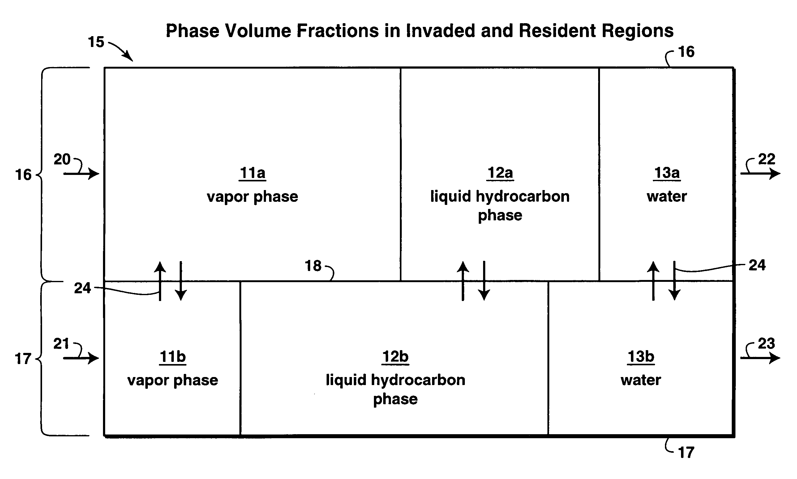
[0092]The Damköhler numbers represent the rate of mixing of components between invaded and resident regions. Results shown in FIGS. 6A through D demonstrate that this invention successfully reproduces the correct limiting behaviors. The MCM phase behavior description in Table 1 was used in this example and the Damköhler numbers were assumed to be Da1=0 for the solvent component and Da2=Da3 for the oil components. The simulation of this example started at a waterflood residual oil saturation of 0.35 and used 25 gridcells in the one-dimensional model.

[0093]FIG. 6A shows that when there is no mixing (oil Damköhler numbers=0), the model correctly predicts that there is pure displacement of the oil with no exchange of components between regions. In FIG. 6A, curve 30 is the fraction of light oil component recovered and curve 31 (which has exactly the same shape as curve 30) is the fraction of heavy oil component recovered. The light and heavy component recovery curves 30 and 31 are identi...

example 3

[0096]FIG. 7 shows experimental data presented in a paper by Blackwell, R. J., Rayne, J. R., and Terry, W. M., “Factors Influencing the Efficiency of Miscible Displacement,”Petroleum Transactions, AIME (1959) 216, 1–8 (referred to hereinafter as “Blackwell et al.”) for a first-contact miscible flood at different values of initial oil / solvent viscosity ratio. The experimental data, which appear as points in FIG. 7, were obtained using homogeneous sand packs and fluids of equal density (to minimize gravity segregation). Experiments were conducted at viscosity ratios of 5, 86, 150 and 375. No water was present in the experiments.

[0097]Also plotted in FIG. 7 are lines that correspond to oil recoveries obtained from simulations using the method of this invention in which the initial oil / solvent viscosity ratio was set at the experimental value, and the coordination number was adjusted to obtain the best possible fit with the experimental data. The Damköhler number was estimated to be on ...


PUM


Abstract

The invention is a method for simulating one or more characteristics of a multi-component, hydrocarbon-bearing formation into which a displacement fluid having at least one component is injected to displace formation hydrocarbons. The first step of the method is to equate at least part of the formation to a multiplicity of gridcells. Each gridcell is then divided into two regions, a first region representing a portion of each gridcell swept by the displacement fluid and a second region representing a portion of each gridcell essentially unswept by the displacement fluid. The distribution of components in each region is assumed to be essentially uniform. A model is constructed that is representative of fluid properties within each region, fluid flow between gridcells using principles of percolation theory, and component transport between the regions. The model is then used in a simulator to simulate one or more characteristics of the formation.

Description

[0001]This application claims the benefit of U.S. Provisional Application No. 60 / 159,035 filed on Oct. 12, 1999.FIELD OF THE INVENTION[0002]This invention relates generally to simulating a hydrocarbon-bearing formation, and more specifically to a method and system for simulating a hydrocarbon-bearing formation under conditions in which a fluid is injected into the formation to displace resident hydrocarbons. The method of this invention is especially useful in modeling the effects of viscous fingering and channeling as the injected fluid flows through a hydrocarbon-bearing formation.BACKGROUND OF THE INVENTION[0003]In the primary recovery of oil from a subterranean, oil-bearing formation or reservoir, it is usually possible to recover only a limited proportion of the original oil present in the reservoir. For this reason, a variety of supplemental recovery techniques have been used to improve the displacement of oil from the reservoir rock. These techniques can be generally classifi...

Claims


Application Information

Patent Timeline
Patent Type & Authority Patents(United States)
IPC IPC(8): G06G7/48E21B43/16E21B49/00
CPCE21B43/164E21B49/00E21B43/166
Inventor HUH, CHUNTELETZKE, GARY F.NIVARTHI, SRIRAM S.
Owner EXXONMOBIL UPSTREAM RES CO
Why Eureka
Try Eureka