Method for forming low-carbon CVD film for filling trenches

a cvd film, low-carbon technology, applied in the direction of solid-state diffusion coating, coating, energy-based chemical/physical/physical-chemical processes, etc., can solve the problems of poor chemical resistance, high leakage current, and other negative effects, and achieve the effect of reducing the quality of the film, reducing the cost of production, and improving the quality of the produ

Active Publication Date: 2010-06-10
ASM JAPAN
View PDF43 Cites 359 Cited by
  • Summary
  • Abstract
  • Description
  • Claims
  • Application Information

AI Technical Summary

Problems solved by technology

On the other hand, post-treatment applied after film forming causes carbon to dissociate and the film density in STI trenches to become lower (lower density here refers to opening of numerous void-like holes or shrinking of film in trenches having surface irregularities), while at the same time the film quality also drops (leading to high leak current, poor chemical resist

Method used


Image

  • Method for forming low-carbon CVD film for filling trenches
  • Method for forming low-carbon CVD film for filling trenches
  • Method for forming low-carbon CVD film for filling trenches

Examples


example

[0083]Experiments were conducted as described below. The results are indicated in tables below. In the tables, a downward pointing arrow indicates that the immediately overlying entry is carried over to the box containing the arrow. In these experiments, a plasma CVD apparatus (Eagle® 12, ASM Japan) shown in FIG. 4 was used.

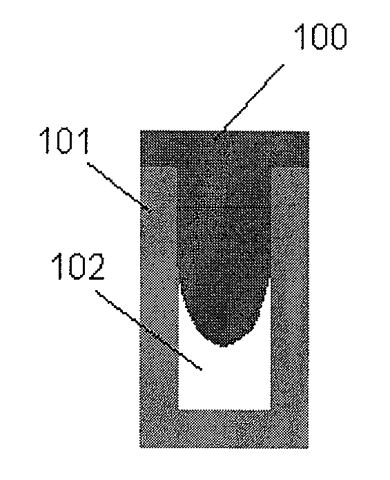
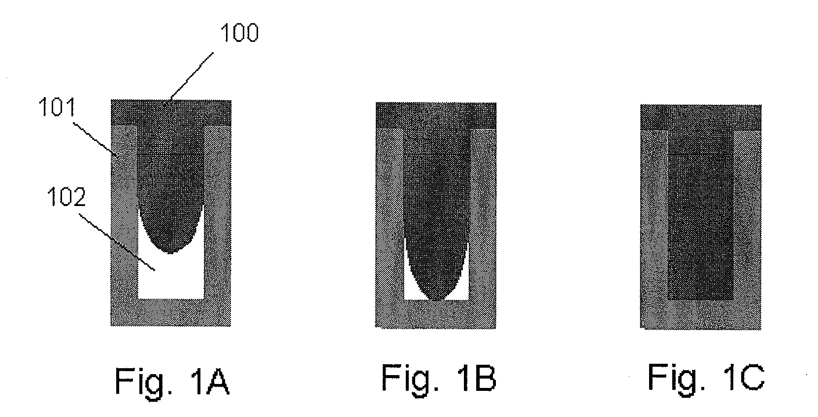
[0084]An insulation film was formed on and filled in an irregular surface of SiN formed on a Si wafer (300 mm), the surface including a trench having a width of 20-500 nm (a depth of about 100-500 nm). UV treatment was conducted in the UV treatment apparatus shown in FIG. 5. Thermal treatment was conducted in the batch-type furnace chamber shown in FIG. 6. A wet etch evaluation was conducted as follows: After a film was deposited on a substrate and subjected to post deposition treatment, a trench filled with the film was vertically cut to show a vertical cross section of the trench and then submerged in an undiluted liquid of LAL500 (manufactured by Stella-Chemif...

examples 1 to 20

[0094]Film was filled under the conditions shown in Table 1. Recipe 1 in the table corresponds to the recipe shown in FIG. 8, recipe 2 corresponds to the recipe shown in FIG. 9 and recipe 3 corresponds to the recipe shown in FIG. 10. Under each recipe, the He flow rate in the gas setting step was 4 SLM and pressure was 533 Pa. In the initial film improvement step, the power output at the start of RF application was 50 W, which was then lowered to 30 W. The durations of respective steps were as follows: 20 seconds for the gas setting step (S1), 10 seconds for the initial film improvement step (S2) and 60 seconds for the film forming step (S3) under recipe 1; and 20 seconds for the gas setting step (S1), 10 seconds for the first period of the initial film improvement step (S2a), 10 seconds for the second period of the initial film improvement step (S2b) and 60 seconds for the film forming step (S3) under recipes 2 and 3. By the way, under recipe 3 the pulsing of material gas was repea...


PUM

PropertyMeasurementUnit
Temperatureaaaaaaaaaa

Abstract

A method of forming a low-carbon silicon-containing film by CVD on a substrate having trenches includes: introducing a silicon-containing compound having three or less hydrocarbon units in its molecule and having a boiling temperature of 35° C. to 220° C.; applying RF power to the gas; and depositing a film on a substrate having trenches wherein the substrate is controlled at a temperature such that components of the silicon-containing compound are at least partially liquidified on the substrate, thereby filling the trenches with the film.

Description

BACKGROUND[0001]1. Field of the Invention[0002]The present invention generally relates to a method for forming a low-carbon CVD film for filling STI structures, for example.[0003]2. Description of the Related Art[0004]Conventional gap-filling methods using a cooling susceptor include those using siloxane material and silazane material, where fluidity can be generated easily as a result of bond of Si and hydrocarbon. On the other hand, post-treatment applied after film forming causes carbon to dissociate and the film density in STI trenches to become lower (lower density here refers to opening of numerous void-like holes or shrinking of film in trenches having surface irregularities), while at the same time the film quality also drops (leading to high leak current, poor chemical resistance and other negative results). As a result, problems occur such as the film becoming vulnerable to damage due to exposure to hydrogen fluoride cleaning solution.[0005]In light of the aforementioned p...

Claims


Application Information

Patent Timeline
IPC IPC(8): B01J19/12
CPCC23C16/045C23C16/36H01L21/0223H01L21/02126C23C16/56
Inventor FUKAZAWA, ATSUKITAZAWA, HISASHIONIZAWA, SHIGEYUKI
Owner ASM JAPAN
Why Eureka
Try Eureka