

Surface coating method for hydrophobic and superhydrophobic treatment in atmospheric pressure plasma
a surface coating and hydrophobic treatment technology, applied in the direction of coating, chemical vapor deposition coating, plasma technique, etc., can solve the problems of large cost increase, inability to apply techniques to mass-production industries, and difficult control of process conditions for fine treatmen
- Summary
- Abstract
- Description
- Claims
- Application Information
AI Technical Summary
Benefits of technology
Problems solved by technology
Method used
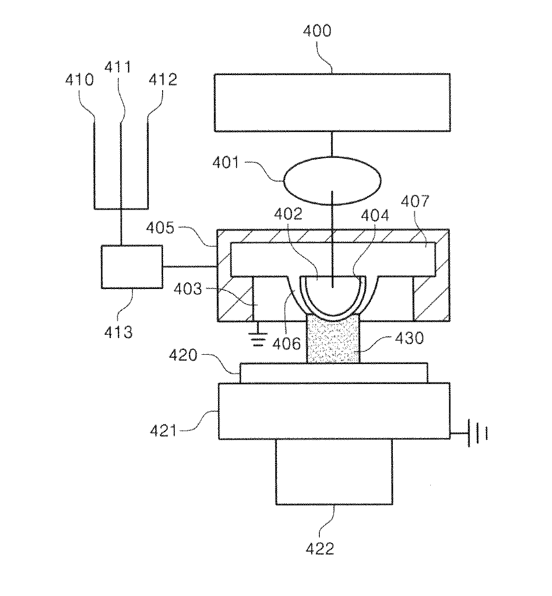
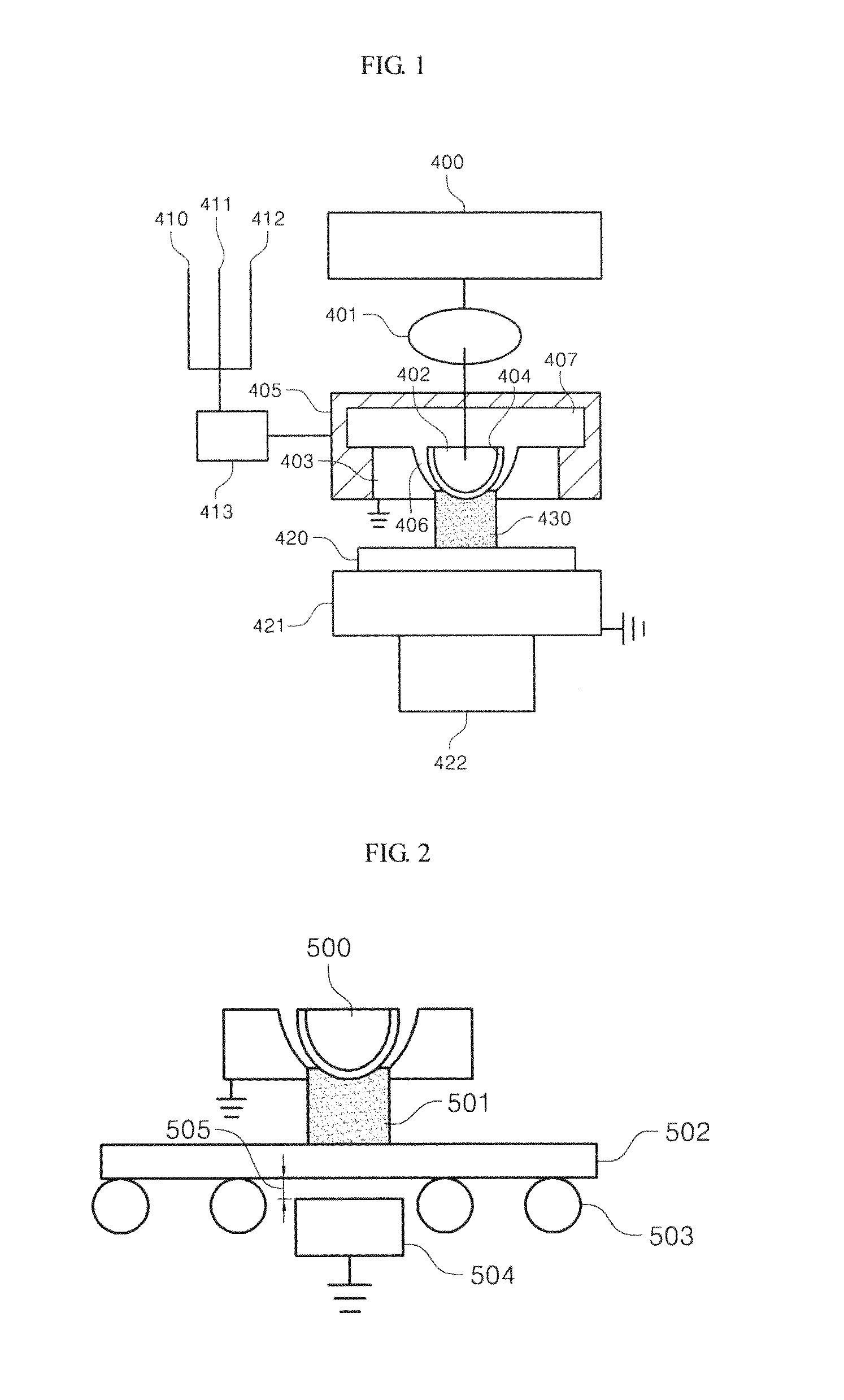
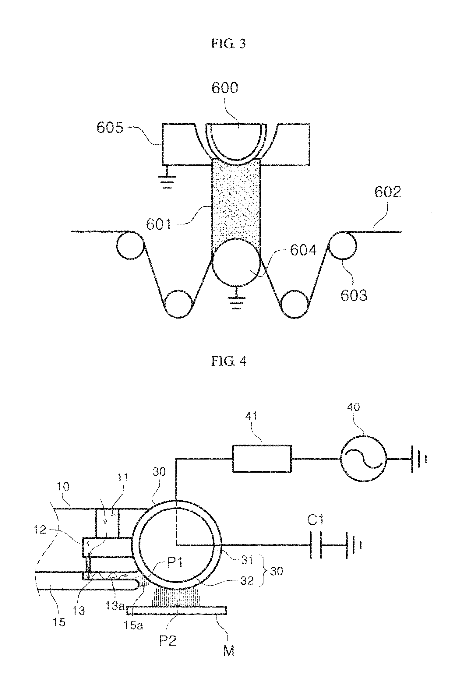
Image

Examples
example 1
[0068]
Purpose: Super-hydrophobicityInert gas: He (10 liter / min)Frequency: 13.56 MHzReaction gas: CF4 (15 sccm),Power: 250 WH2 (5 sccm)Workpiece: Copper sheetNumber of times of treatment: 15 timesContact angle after processing:Processing rate: 10 mm / sec171°
example 2
[0069]
Purpose: Super-hydrophobicityInert gas: He (10 liter / min)Frequency: 13.56 MHzReaction gas: CF4 (15 sccm),Power: 250 WCH4 (5 sccm)Workpiece: Aluminum sheetNumber of times of treatment: 15 timesContact angle after processing:Processing rate: 10 mm / sec168°
example 3
[0070]
Purpose: Super-hydrophobicityInert gas: He (10 liter / min),Frequency: 13.56 MHzAr (1 liter / min)Power: 250 WReaction gas: CF4 (10 sccm),Workpiece: GlassH2 (5 sccm)Contact angle after processing:Number of times of treatment: 10 times157°Processing rate: 10 mm / sec
PUM
| Property | Measurement | Unit |
|---|---|---|
| frequency | aaaaa | aaaaa |
| contact angle | aaaaa | aaaaa |
| size | aaaaa | aaaaa |
Abstract
Description
Claims
Application Information