Automatic inflatable vest

a vest and automatic technology, applied in the field of vests, can solve the problems of serious injury, serious injury or death, etc., and achieve the effect of reducing the impa

Inactive Publication Date: 2006-03-07
TAKEUCHI KENJI
View PDF15 Cites 17 Cited by
  • Summary
  • Abstract
  • Description
  • Claims
  • Application Information

AI Technical Summary

Benefits of technology

[0010]Moreover, according to the second structure of the present invention, a vest having a vest-like appearance with fasteners in its normal condition, provided with a expandable section extending along a line of bend when expanding, and having a plurality of expansion air chambers with a gas injection air line which are housed in said expandable section, wherein the expandable section is formed at the collar part of the vest and the expansion air chambers are formed in a hood-like shape and housed. Thereby, it is possible to protect not only the cervical vertebra but also the entire head, especially the occipital region.
[0011]In the present invention, under such a circumstance that one end of a key is fixed to a vehicle such as a two-wheeled vehicle and the other end is mounted on the body with the safety device released. When the body of a driver / passenger falls from a vehicle such as a two-wheeled vehicle, the key physically fulls away from the body automatically triggers an activating device, and carbon dioxide fills the expansion air chambers by an activating pin breaking through the mouth of the carbon dioxide cylinder. When the driver / passenger wearing it collides with an object, a mechanism in which the expansion air chambers protect the entire body and cushion the impact is utilized.

Problems solved by technology

Generally, traffic accidents of two-wheeled vehicles or the like in which for various reasons a driver / passenger falls from the vehicle and strikes a construction on a road, the road surface, or a wall surface often causing serious injury or death, contusions of the whole_body, rupture of the neck, the spine, the sternum, etc., rupture of organs and so on, have been an existing social problem.
However, focusing on the conventional vests, the neck or spine part of the body is covered merely by a T-shaped expansion air chamber, as exemplifled in FIG. 6; therefore, there is injury to the part of the body where there is no expansion air chamber due to displacement in a linear expansion air chamber at the spine part at the time of the fall, resulting a risk of a serious injury.

Method used


Image

  • Automatic inflatable vest
  • Automatic inflatable vest
  • Automatic inflatable vest

Examples


Embodiment Construction

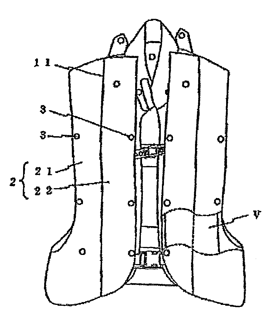
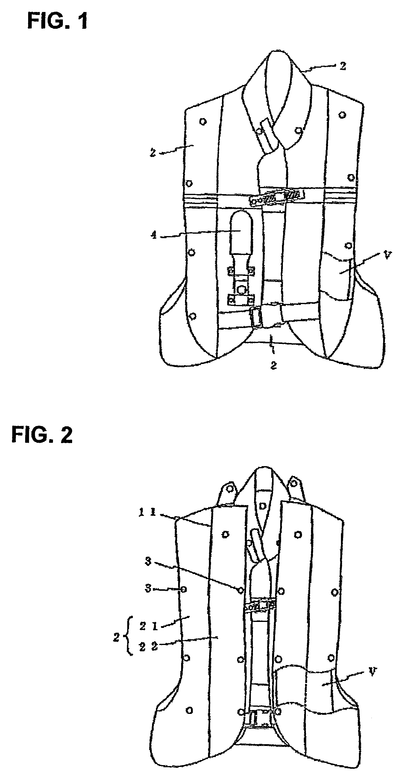
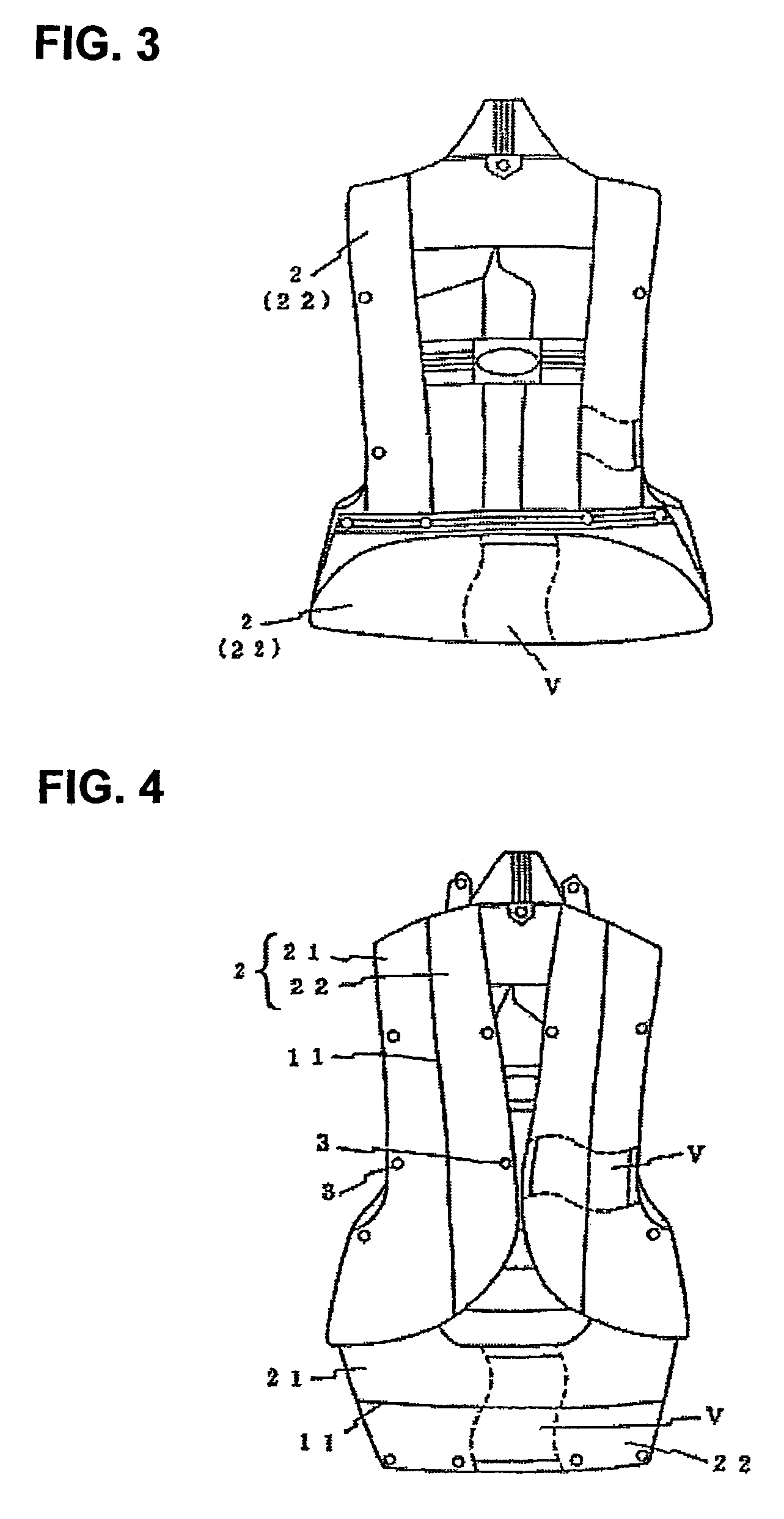
[0019]Hereinafter, embodiments of the present invention will be explained with reference to drawings of the embodiments. FIG. 1 is a front view of an automatic inflatable vest of the present invention; FIG. 2 is a front view, in an opened position, of an expandable section provided to the chest part of the automatic inflatable vest according to the present invention; FIG. 3 is a rear view of the automatic inflatable vest according to the present invention; FIG. 4 is a rear view in an opened position of the expandable section provided to the waist part and the back part of the automatic inflatable vest according to the present invention; FIG. 5 is a front view of the enlarged element in an opened position of the expandable section provided at the collar of the automatic inflatable vest according to the present invention; FIG. 6 is a front view of the enlarged element showing another embodiment of the collar of the automatic inflatable vest according to the present invention; and FIG....


PUM


Abstract

A vest to be worn by a driver/passenger of a two-wheeled vehicle or the like provided with a plurality of air chambers which are folded and housed wherein the air chambers instantaneously expand in two stages by being filled with carbon dioxide gas injected through a carbon dioxide gas cylinder connected to the activating device, creating a buffer effect to cushion the impact on the driver/passenger, who is thrown out onto a road surface, a construction on the road, a wall surface, or the like, which is a circumstance typical to traffic accident disasters of two-wheeled vehicles or the like.

Description

BACKGROUND OF THE INVENTION[0001]1. Field of the Invention[0002]The invention relates to a vest having the equipment of a safety vest in an inactivated state as a life protection device for a driver / passenger of a two-wheeled vehicle and expansion air chambers to be a buffer mechanism when activated, more specifically, a vest to be activated as an emergency life protection device by injecting carbon dioxide gas into the expansion air chambers within the vest from a carbon dioxide cylinder.[0003]2. Prior Arts[0004]Generally, traffic accidents of two-wheeled vehicles or the like in which for various reasons a driver / passenger falls from the vehicle and strikes a construction on a road, the road surface, or a wall surface often causing serious injury or death, contusions of the whole_body, rupture of the neck, the spine, the sternum, etc., rupture of organs and so on, have been an existing social problem.[0005]Under such circumstances, as a life protection device for a driver / passenger...

Claims


Application Information

Patent Timeline
Patent Type & Authority Patents(United States)
IPC IPC(8): A41D1/04A41D13/018A41D13/00A41D31/00A41D31/02B01J7/00
CPCA41D13/018Y10S2/03A41D1/04
Inventor TAKEUCHI, KENJI
Owner TAKEUCHI KENJI
Why Eureka
Try Eureka