

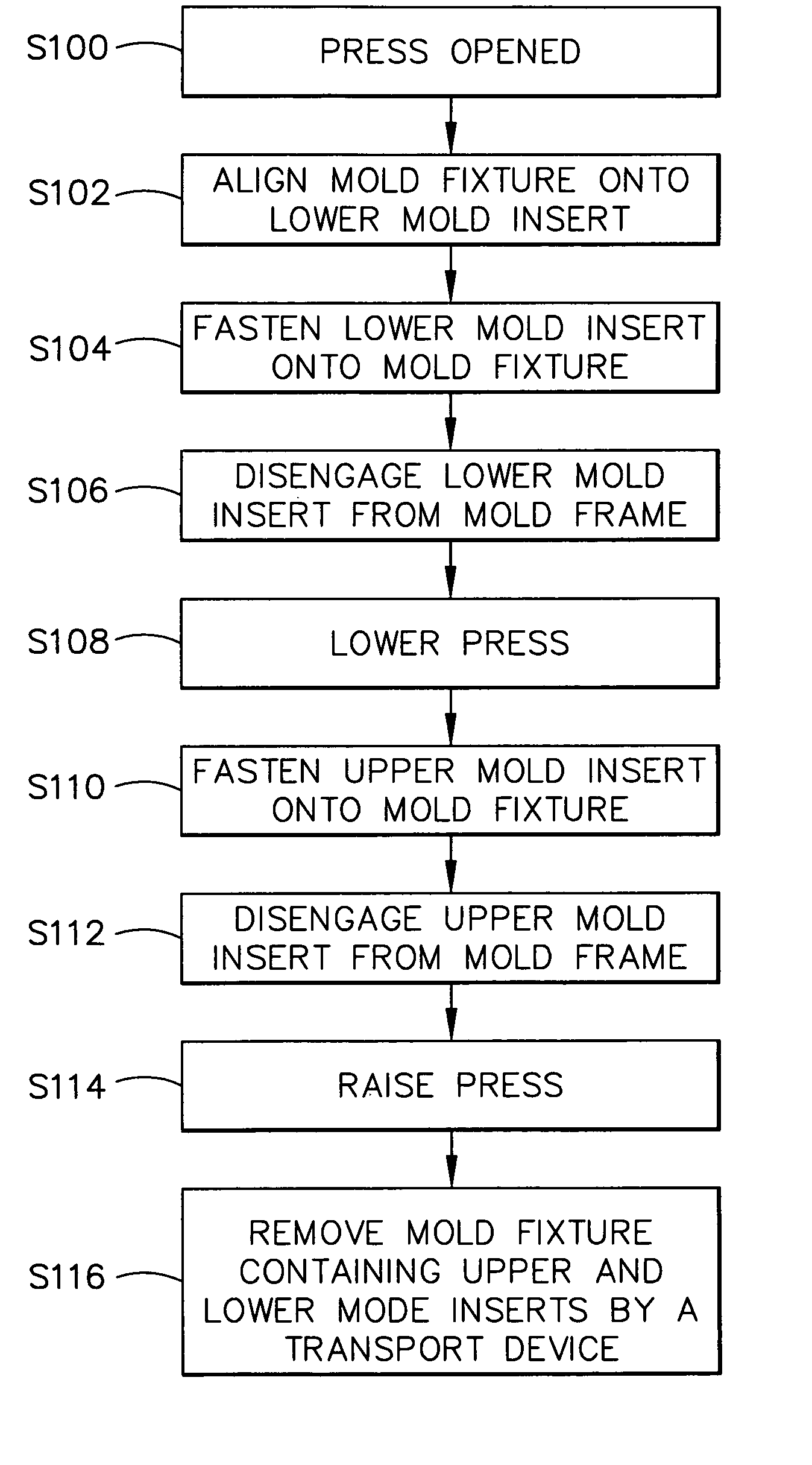
Method of extracting and inserting upper and lower molds
- Summary
- Abstract
- Description
- Claims
- Application Information
AI Technical Summary
Benefits of technology
Problems solved by technology
Method used
Image

Examples
Embodiment Construction
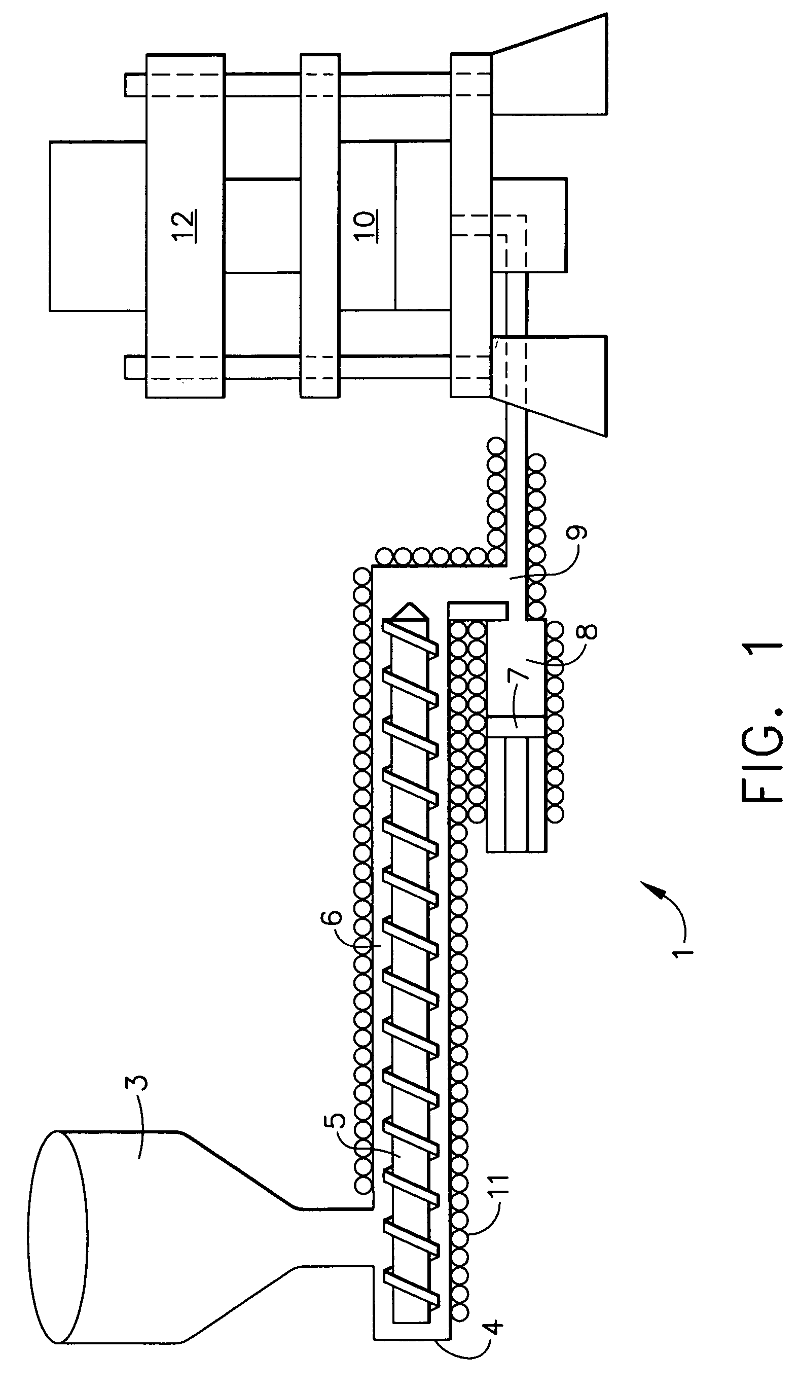
[0025]FIG. 1 shows an example of a resin transfer molding apparatus 1, which is suitable for implementing principles of the present invention. Raw material, typically resin, is loaded into a hopper 3 attached to an extruder 4. An extruder screw 5 feeds resin from the hopper 3 and progressively heats the resin as it is transported down the length of a barrel 6. The resin is then transported into an accumulator 8. The resin melt pressure created by the extruder 4 forces a piston 7 inside the accumulator 8 back to a desired position. Once the desired volume of resin has been accumulated, the accumulator piston 7 moves forward and forces the volume of resin through a transfer pipe 9 into a cavity of a mold 10. Temperature is controlled using heat exchange coils 11. An arrangement of valves (not depicted) is provided in relation to the transfer pipe 9 to control flow and backflow of the resin, respectively. The part (or preform) to be infiltrated is contained within the mold 10. The mold...
PUM
 Abstract
Description
Claims
Application Information