Bypass for a hydraulic device

a technology of hydraulic device and bypass, which is applied in the direction of fluid couplings, clutches, gearing elements, etc., can solve the problems of inability to manually move the vehicle, prior art design drawbacks, and uncontrolled free-wheeling of the vehicl

Inactive Publication Date: 2006-03-07
HYDRO GEAR PARTNERSHIP
View PDF18 Cites 3 Cited by
  • Summary
  • Abstract
  • Description
  • Claims
  • Application Information

AI Technical Summary

Benefits of technology

[0010]It is a further object of this invention to provide an improved HST design which gives the user a wider neutral band, through use of such a switch in connection with the control mechanism of the v...

Problems solved by technology

However, in most designs this neutral band is very narrow, as it is dictated by the mechanical design of the unit and the user's ability to mechanically locate the neutral area through use of a shift lever or foot pedal system.
For example, when the vehicle is stopped, the oil in the closed circuit provides hydraulic braking, making it impossible to manually move the vehicle.
However, such prior art designs have draw...

Method used


Image

  • Bypass for a hydraulic device
  • Bypass for a hydraulic device
  • Bypass for a hydraulic device

Examples


Embodiment Construction

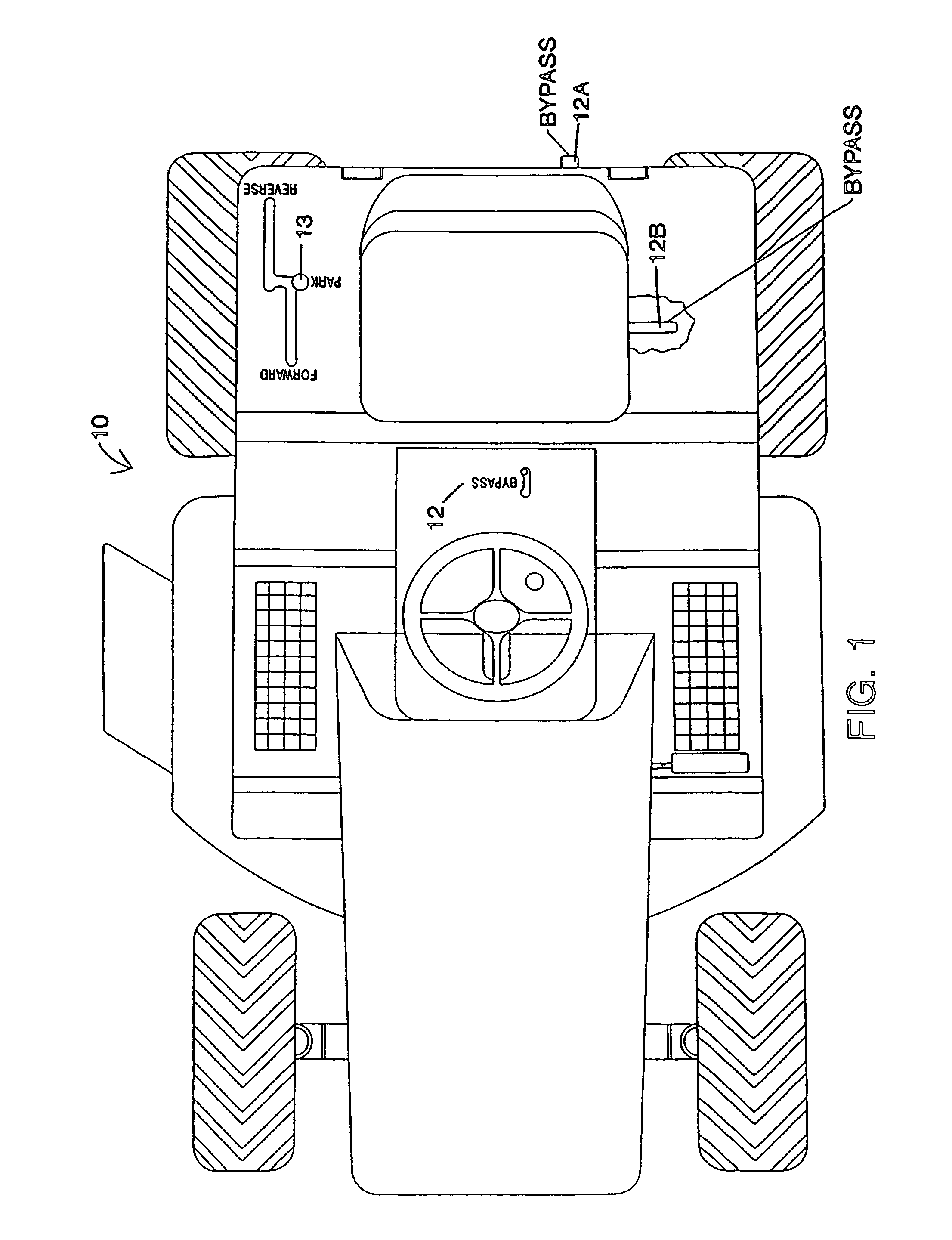
[0036]FIG. 1 is a view of a typical vehicle using a integrated hydrostatic transmission, namely tractor 10, showing various locations of control mechanisms for mechanical bypass units. Different tractor manufacturers have different preferences for location of the mechanical bypass actuator, making it difficult for an IHT manufacturer to design a single unit for all uses without expensive design modifications or use of additional linkages to accommodate such uses. For example, the bypass 12 may be located on the panel immediately in front of the seat. Other manufacturers prefer to have it mounted in location 12A at the rear of the tractor, while others require it to be located under the tractor seat at location 12B. Control lever 13 is generally used to control direction and speed of the vehicle.

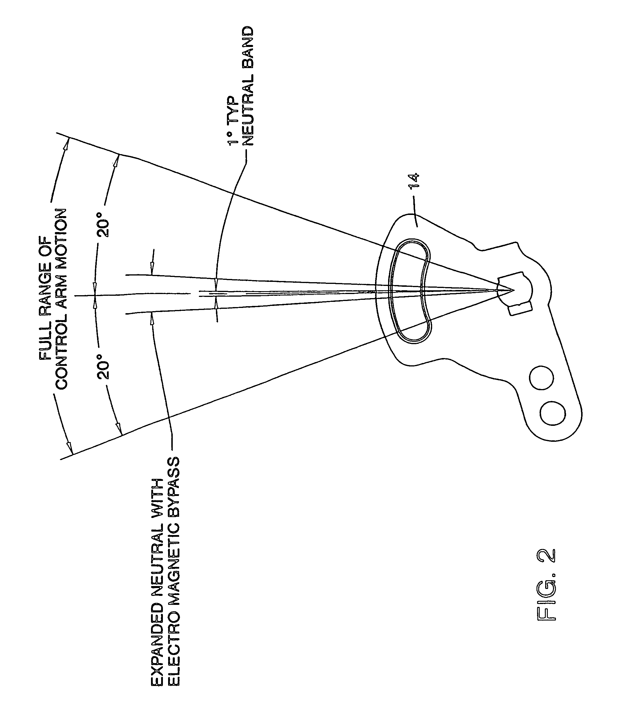
[0037]A typical control arm 14 is shown in FIG. 2, and is generally attached to the external housing of the IHT unit. The tractor manufacturer will generally attach its own levers and linkage...


PUM


Abstract

A bypass mechanism is provided for use in a hydrostatic transmission, to enable the user to open or close a valve between the two pressure sides of the hydraulic circuit of the transmission. An electrical mechanism is positioned to open or close the valve based on a signal which may be generated by a switch associated with the hydrostatic transmission.

Description

CROSS-REFERENCE TO RELATED APPLICATIONS[0001]This application is a continuation of U.S. application Ser. No. 10 / 465,041 filed Jun. 19, 2003 now U.S. Pat. No. 6,735,943, which is a continuation of U.S. application Ser. No. 10 / 036,835 filed Dec. 21, 2001 now U.S. Pat. No. 6,588,206, which is a continuation of U.S. application Ser. No. 09 / 627,569 flied Jul. 28, 2000, now U.S. Pat. No. 6,332,317, which is a continuation of U.S. application Ser. No. 09 / 223,673 filed Dec. 30, 1998, now U.S. Pat. No. 6,145,312, all of which are incorporated herein by reference.BACKGROUND[0002]This invention relates to a electromechanical bypass for use in a hydrostatic transmission (“HST”). Hydrostatic transmissions are well known in the art, and are more fully described in, e.g., U.S. Pat. No. 5,314,387, which is incorporated by reference herein. This invention can also be adapted for use in an integrated hydrostatic transmission (“IHT”) incorporating gearing and axles within a single housing.[0003]In gen...

Claims


Application Information

Patent Timeline
IPC IPC(8): F16D31/02
CPCF16H61/40F16H61/4043F16H61/4035
Inventor HAUSER, RAYMONDHOLDER, LONNIE E.
Owner HYDRO GEAR PARTNERSHIP
Why Eureka
Try Eureka