
Lubrication supply control system

a control system and lubrication technology, applied in the direction of auxilary lubrication, lubrication of crankcase compression engines, machines/engines, etc., can solve the problems of increased engine load, difficult control of mechanical pumps, and inability to provide highly precise amounts of lubrican

Active Publication Date: 2006-03-07
YAMAHA MARINE KK
View PDF13 Cites 14 Cited by
  • Summary
  • Abstract
  • Description
  • Claims
  • Application Information

AI Technical Summary

Benefits of technology

[0019]For purposes of summarizing the invention, certain aspects, advantages and novel features of the invention have been described herein above. Of course, it is to be understood that not necessarily all advantages disclosed or taught herein may be achieved in accordance with any particular embodiment of the invention. Thus, the invention may be embodied or carried out in a manner that achieves or optimizes one advantage or group of advantages as disclosed or taught herein without necessarily achieving other advantages as may be disclosed, taught or suggested herein.

Problems solved by technology

Such mechanical pumps, however, are not easily controlled to provide highly precise amounts of lubricant in response to engine operations.
Also, if the engine powers a watercraft, the engine load can increase when the watercraft proceeds against wind.

Method used


Image

  • Lubrication supply control system
  • Lubrication supply control system
  • Lubrication supply control system

Examples


Embodiment Construction

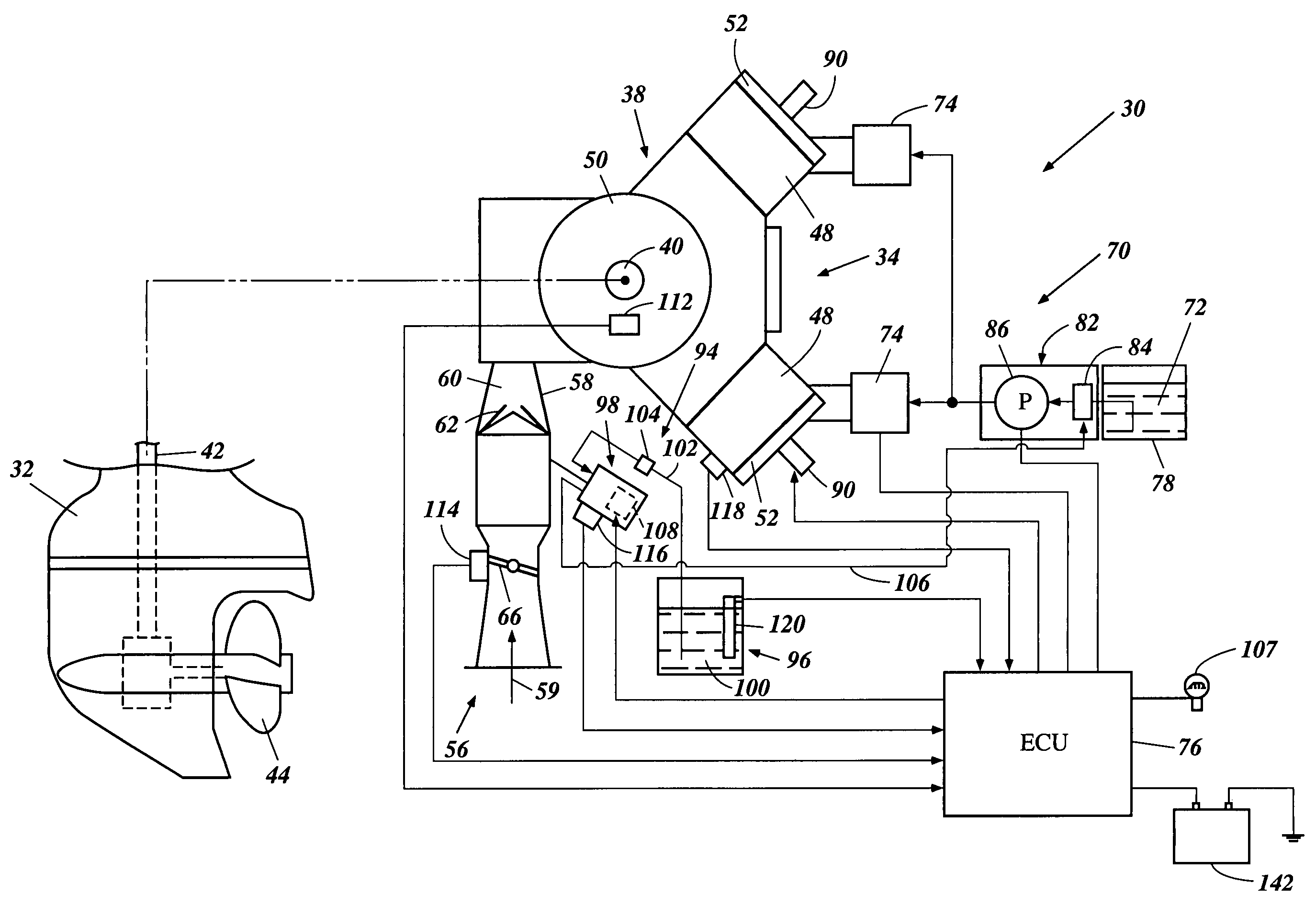
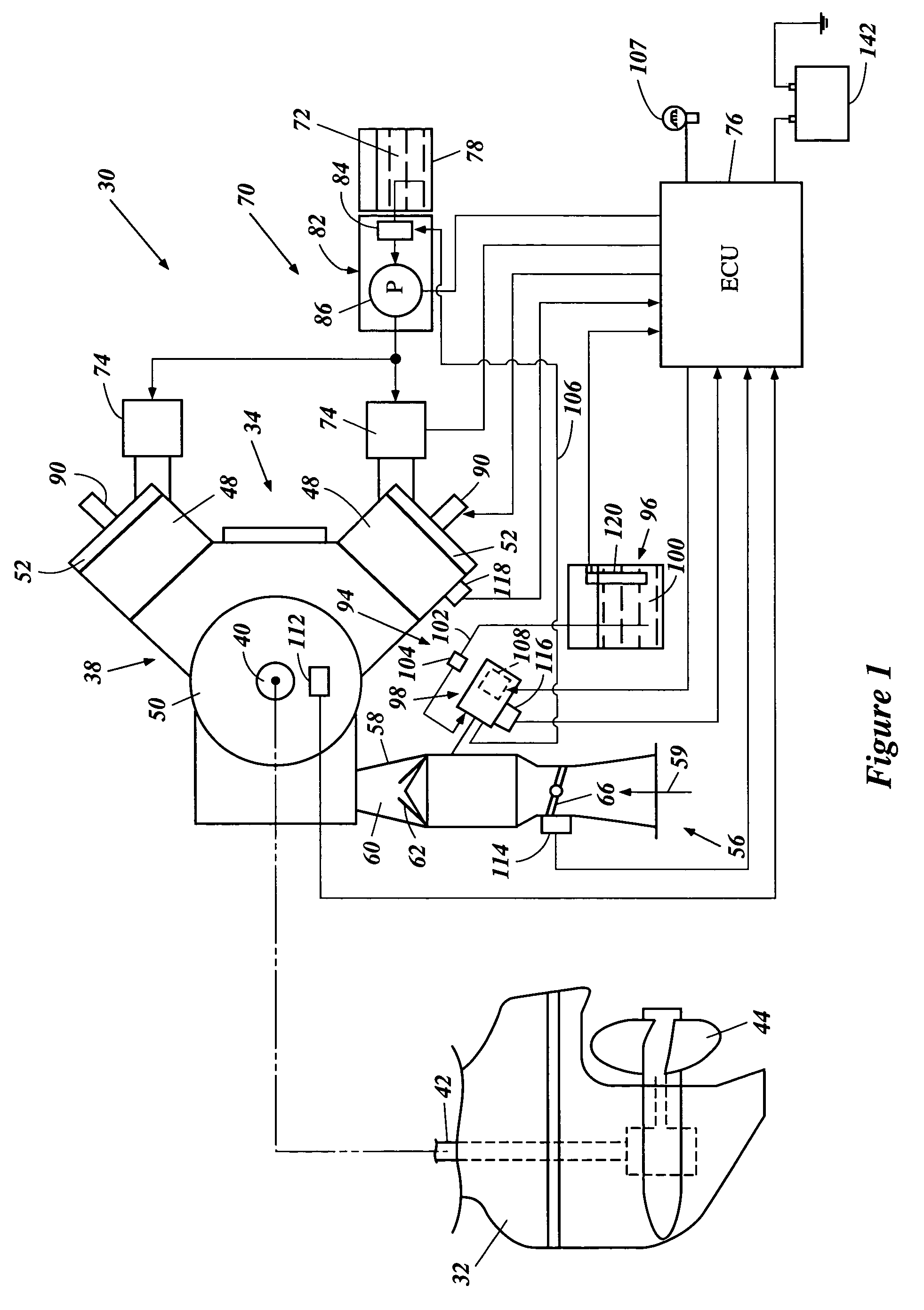
[0028]The present lubrication system described below has particular utility in the context of a two-cycle engine for an outboard motor, and thus, is described in the context of such an outboard motor. The lubrication system, however, can be used with other types of engines employed by any machines whatsoever using engine power such as, for example, watercrafts (e.g., personal watercrafts), land vehicles (e.g., motorcycles) and utility machines (e.g., lawn mowers).

[0029]With reference to FIG. 1, an outboard motor 30 has a bracket assembly comprising a swivel bracket and a clamping bracket which are typically associated with a housing unit 32. The bracket assembly can mount the outboard motor 30 on an associated watercraft. The outboard motor 30 includes a power head that is positioned above the housing unit 32. The power head comprises a protective cowling assembly and an internal combustion engine 34. An engine support is unitarily or separately formed atop the housing unit 32 and f...


PUM


Abstract

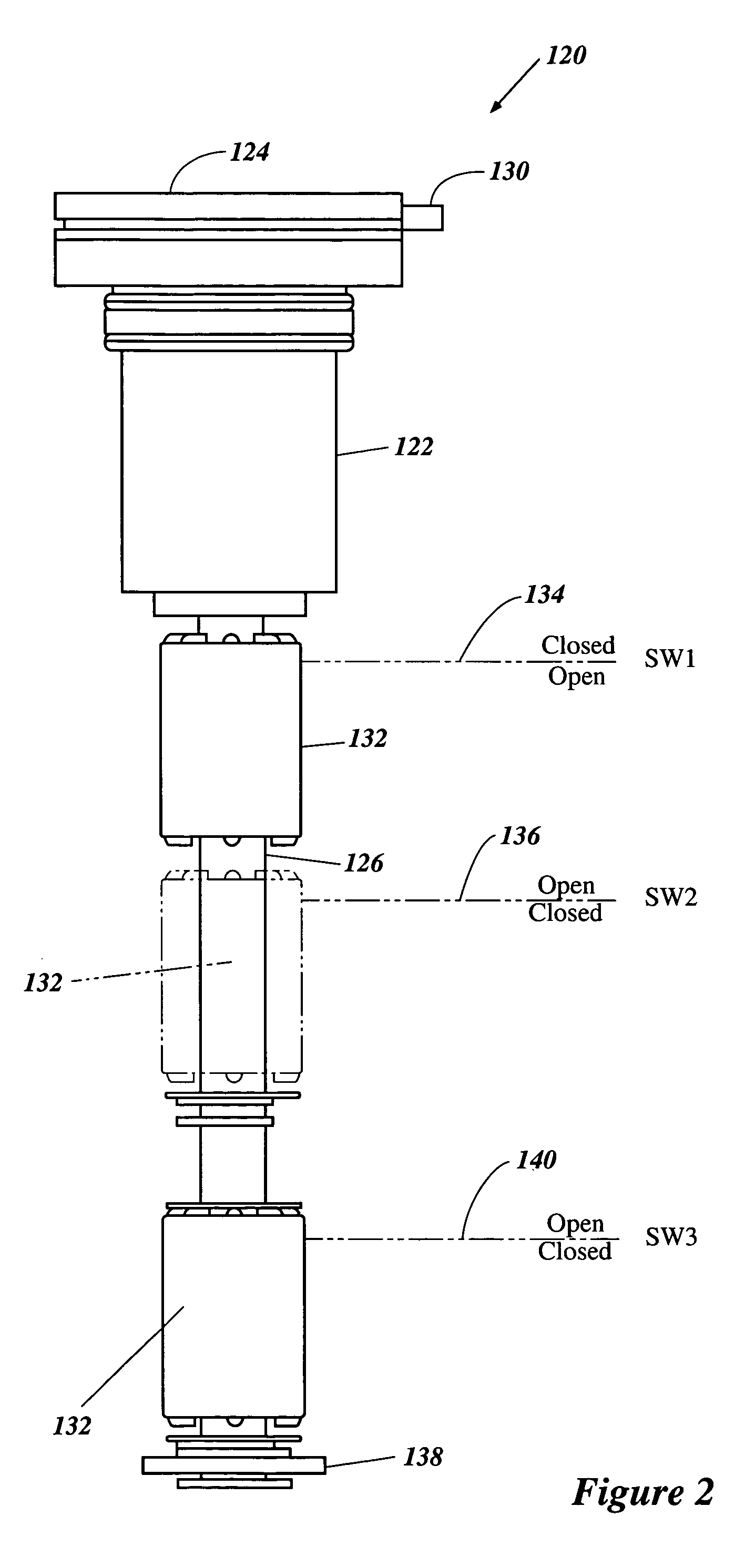
An engine has a lubrication system to lubricate at least a portion of the engine with lubricant. The lubrication system has a lubrication pump that periodically pressurizes the lubricant toward the portion of the engine. A first sensor senses an engine speed. A second sensor senses an engine load. A third sensor senses a temperature of the lubricant or the engine. A control device controls the lubrication pump. The control device determines a frequency of periodic pressurization by the lubrication pump based upon outputs from the first and second sensors. The control device determines a pressurization time of the lubrication pump based upon at least one of outputs from the first sensor, second sensor, third sensor, and a battery voltage.

Description

PRIORITY INFORMATION[0001]This application is based on and claims priority under 35 U.S.C. §119 to Japanese Patent Application No. 2002-321470, filed on Nov. 5, 2002, the entire contents of which is hereby expressly incorporated by reference herein.FIELD OF THE INVENTION[0002]The present application relates to a lubrication system for an engine, and more particularly a lubrication system that incorporates a lubrication pump that pressurizes lubricant to a portion of an engine. The lubrication system is particularly useful in a two-stroke engine.DESCRIPTION OF THE RELATED ART[0003]In all fields of engine design, there is an increasing emphasis on obtaining more effective emission control. Recent two-cycle engines, therefore, incorporate a lubricant pump to deliver a desired amount of lubricant to lubricate internal portions of the engines. Mechanically operated pumps can be used as the lubricant pump. Such mechanical pumps, however, are not easily controlled to provide highly precise...

Claims


Application Information

Patent Timeline
Patent Type & Authority Patents(United States)
IPC IPC(8): F01M1/00F01M1/14F01M1/16F01M11/12
CPCF01M1/16F01M1/14
Inventor FUJINO, KENICHI
Owner YAMAHA MARINE KK
Learn More