Foot mobility aid

a technology for walking aids and feet, applied in walking aids, physical therapy, travelling accessories, etc., can solve problems such as not disclosing a new foot mobility aid

Inactive Publication Date: 2006-03-07
THROWER MARTHA
View PDF22 Cites 19 Cited by
  • Summary
  • Abstract
  • Description
  • Claims
  • Application Information

AI Technical Summary

Benefits of technology

[0022]Still yet another object of the present invention is to provide a new foot mobility aid that paralyzed in a leg to move that leg when walking or for positioning the leg when sitting or getting up from a seated position.
[0023]Even still another object of the present invention is to provide a new foot mobility aid that helps a user with limited leg mobility exercise their leg by walking.

Problems solved by technology

While these devices fulfill their respective, particular objectives and requirements, the aforementioned patents do not disclose a new foot mobility aid.

Method used


Image

  • Foot mobility aid
  • Foot mobility aid
  • Foot mobility aid

Examples


Embodiment Construction

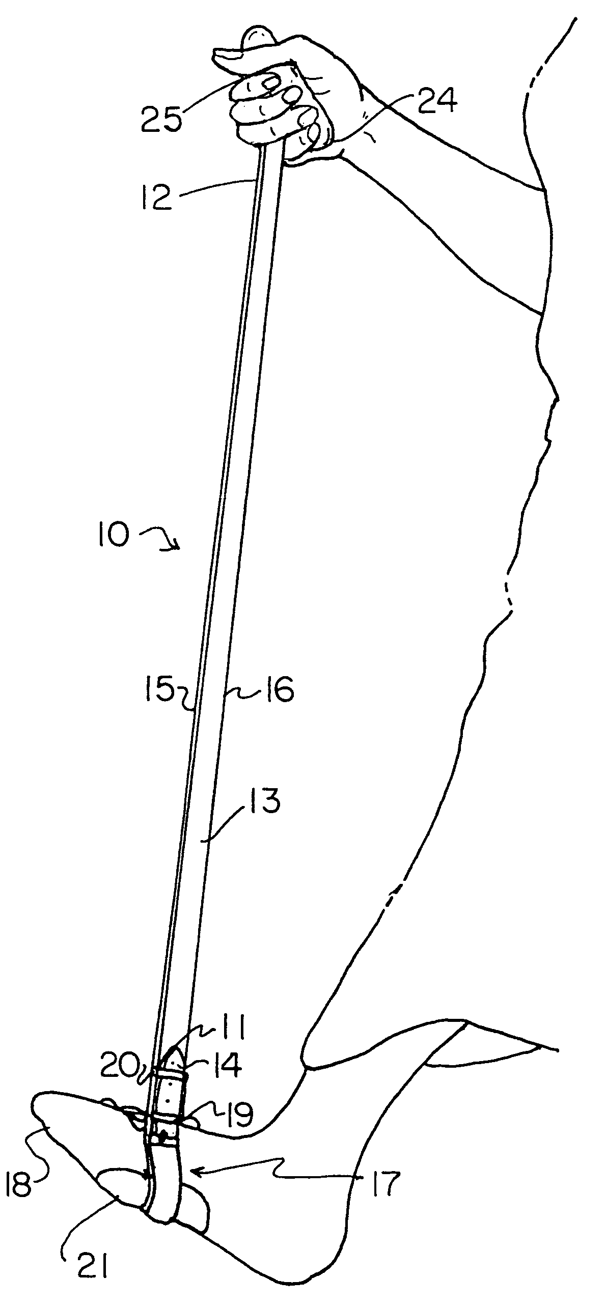
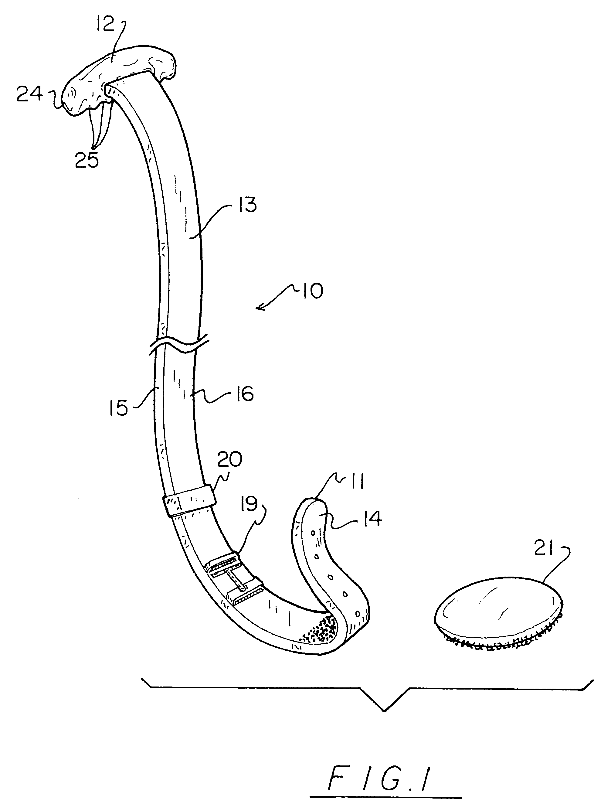
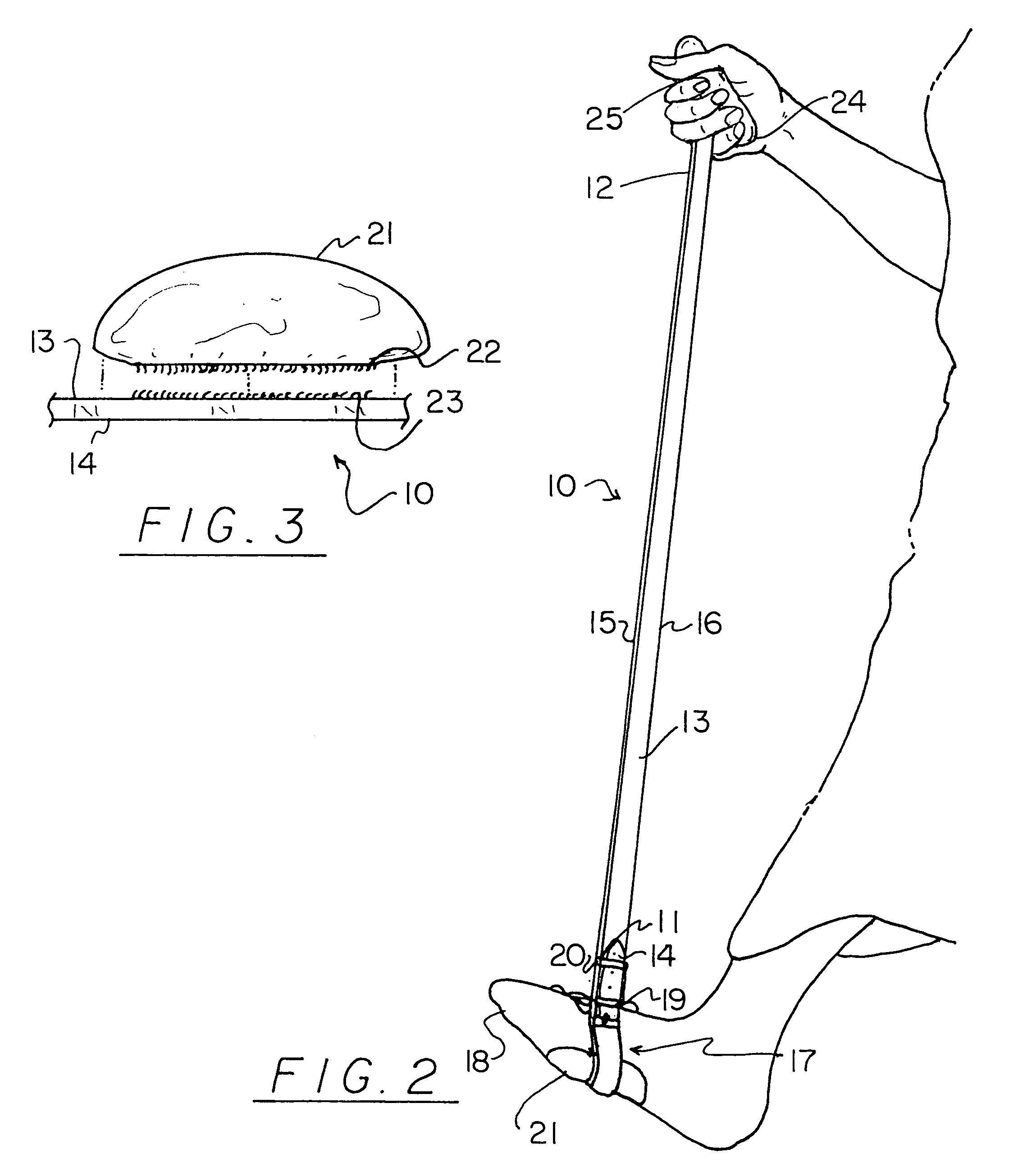
[0029]With reference now to the drawings, and in particular to FIGS. 1 through 3 thereof, a new foot mobility aid embodying the principles and concepts of the present invention will be described.

[0030]As best illustrated in FIGS. 1 through 3, the foot mobility aid generally comprises an elongate flexible strap with a pair of opposite ends. One of the ends of the strap is folded back over an adjacent portion of the strap and coupled to the adjacent portion of the strap to form a foot loop for extending the foot of a user therein.

[0031]In closer detail, the foot mobility aid comprises an elongate flexible strap 10 with a pair of opposite ends 11,12. Preferably, the flexible strap has a generally rectangular transverse cross section and has a pair of opposite faces 13,14, and a pair of side edges 15,16 extending between the ends of the strap. The strap has a length defined between the ends of the strap and a width defined between the side edges of the strap. Preferably, the length of t...


PUM


Abstract

A foot mobility aid for helping a user with limited mobility in a leg and foot help move the user's leg and foot when walking. The foot mobility aid includes an elongate flexible strap with a pair of opposite ends. One of the ends of the strap is folded back over an adjacent portion of the strap and coupled to the adjacent portion of the strap to form a foot loop for extending the foot of a user therein.

Description

BACKGROUND OF THE INVENTION[0001]1. Field of the Invention[0002]The present invention relates to devices for aiding the mobility of a user's foot and leg and more particularly pertains to a new foot mobility aid for helping a user with limited mobility in a leg and foot help move the user's leg and foot when walking.[0003]2. Description of the Prior Art[0004]The use of devices for aiding the mobility of a user's foot and leg is known in the prior art. More specifically, devices for aiding the mobility of a user's foot and leg heretofore devised and utilized are known to consist basically of familiar, expected and obvious structural configurations, notwithstanding the myriad of designs encompassed by the crowded prior art which have been developed for the fulfillment of countless objectives and requirements.[0005]Known prior art includes U.S. Pat. No. 4,121,827 by Weider; U.S. Pat. No. 3,828,370 by Ihmels; U.S. Pat. No. Des. 244,869 by Manley et al.; U.S. Pat. No. Des. 207,770 by Los...

Claims


Application Information

Patent Timeline
Patent Type & Authority Patents(United States)
IPC IPC(8): A45B1/00
CPCA61H3/00A61H2205/12A61H2201/1269
Inventor THROWER, MARTHA
Owner THROWER MARTHA
Why Eureka
Try Eureka