Breathing mask with integrated suction area

a breathing mask and integrated technology, applied in breathing masks, breathing filters, breathing protection, etc., can solve the problems of compromising the recognizability of the patient's face, increasing the technical effort and consequently the cost, and hindering the mobility of the user of the mask, so as to achieve high wear comfort and high safety

Inactive Publication Date: 2009-01-27
DRAGERWERK AG
View PDF15 Cites 82 Cited by
  • Summary
  • Abstract
  • Description
  • Claims
  • Application Information

AI Technical Summary

Benefits of technology

[0009]The object of the present invention is to provide a breathing mask for breathing support devices with high wear comfort and high safety against accidental coverage of the suction opening, which said breathing support devices are to be worn by the patient.
[0010]Some of the CPAP devices currently available are so advanced in terms of their type of construction, their noise generation and their energy consumption that it is possible to wear these devices in an adapted form directly at the patient. The advantage of such devices is the elimination of the mobility restriction and that it is possible to integrate the gas routing into a device and mask combination.
[0017]It is advantageous if the limiting surface of the mask body is made at least partially of a textile, gas-permeable structure. As a result, a possibly desired filter action can be achieved as a result in the area acting as a suction opening in a very simple manner.
[0019]In an advantageous embodiment, the separated volume area in the interior of the mask is limited by a flexible wall, which is impermeable to air. To maintain the ability of this volume area to function, it is advantageous if the mask body comprises a shaping support frame, to which the material that forms the outer limitation of the mask body is attached, the support frame being located in the area of the air-impermeable flexible wall between the air-impermeable flexible wall and the material that forms the outer limitation of the mask body. As a result, parts of the support frame can ensure a sufficient distance between the limiting surfaces and prevent the vacuum prevailing during the drawing in of ambient air from narrowing the volume area intended for the drawing in, in the interior of the mask to the extent that suction is hindered.
[0020]It is especially practical if the air-permeable areas of the wall of the mask body, through which ambient air can be drawn in, are arranged along the edge of the mask body in the vicinity of the contact area with the user's face. As a result, different directions of suction can be automatically achieved, as a result of which complete coverage of the entire suction area becomes nearly impossible. Moreover, if the areas through which the expiratory breathing gases can escape into the environment are located mainly in the middle area of the mask body, there is good uncoupling between the air flow being drawn in and the air flow being released.
[0021]Due to the mask body being worn in the vicinity of the nose, the position of the suction area corresponds extensively to the area from which the breathing air is also drawn in during natural breathing without auxiliary means. As a result, the usual safety measures and reflexes of the patient can be utilized. For example, it is highly unlikely that an adult would hinder his breathing by constricting his own nose due to the unfavorable position of the face. After a brief discomfort, he would rather turn his face to the side in order to make unhindered breathing possible. The accidental coverage of the areas of the mask body that are relevant for the drawing in of breathing air can be prevented from occurring by the same reflexes when these areas are arranged sufficiently close to the patient's nose. The dimensioning and the limitation of the suction area as an integrated air filter may make the use of additional filters unnecessary, which means increased wear comfort.

Problems solved by technology

This increases the technical effort and consequently the costs.
Moreover, the flexible tubes hinder the mobility of the user of the mask.
Furthermore, the flexible tubes create a highly technical impression and thus compromise the recognizability of the patient's face with its characteristic zones, especially the area around the eyes.
The risk of coverage of the suction openings represents a possible source of error and a safety risk especially for breathing support during sleep.

Method used


Image

  • Breathing mask with integrated suction area
  • Breathing mask with integrated suction area
  • Breathing mask with integrated suction area

Examples


Embodiment Construction

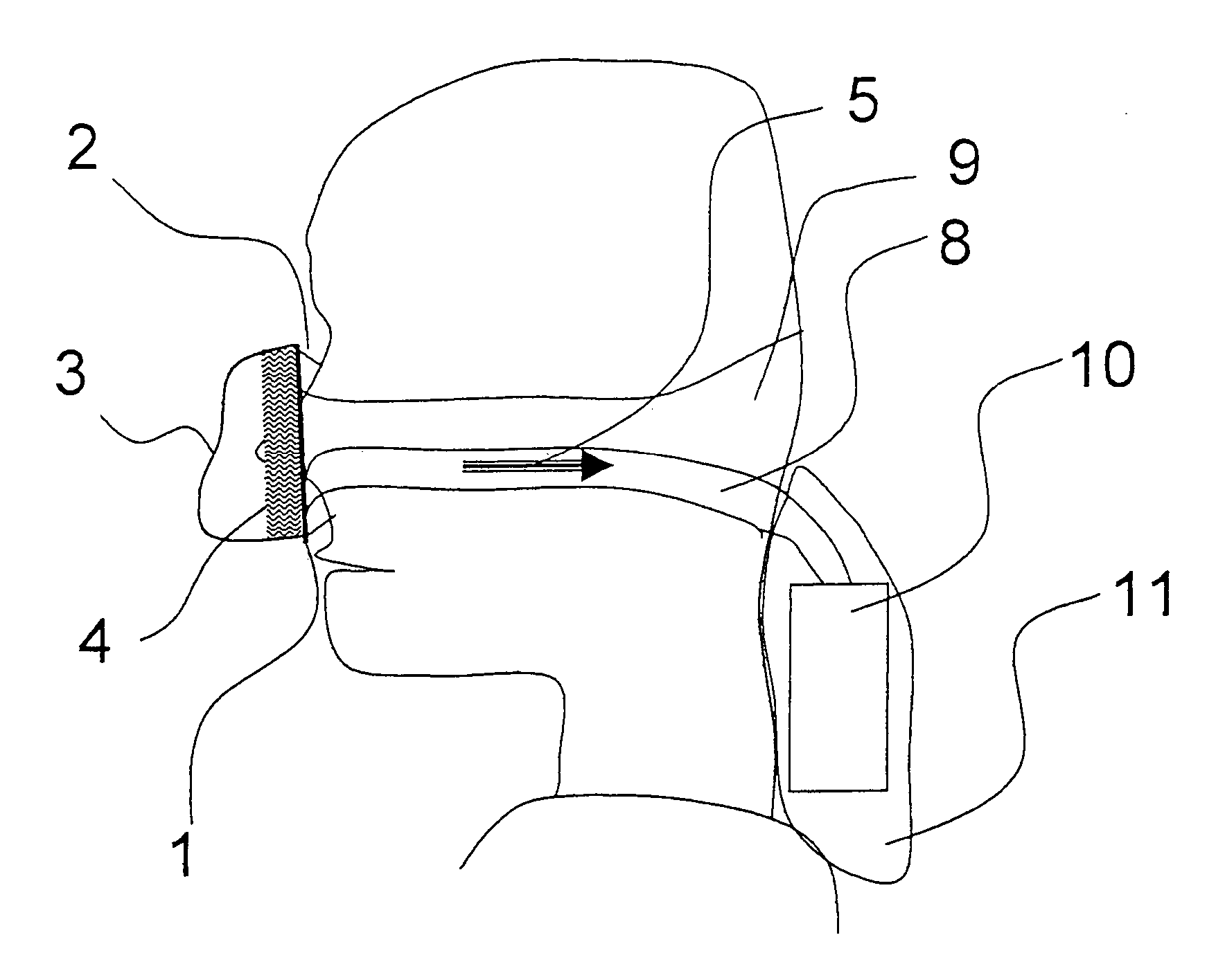
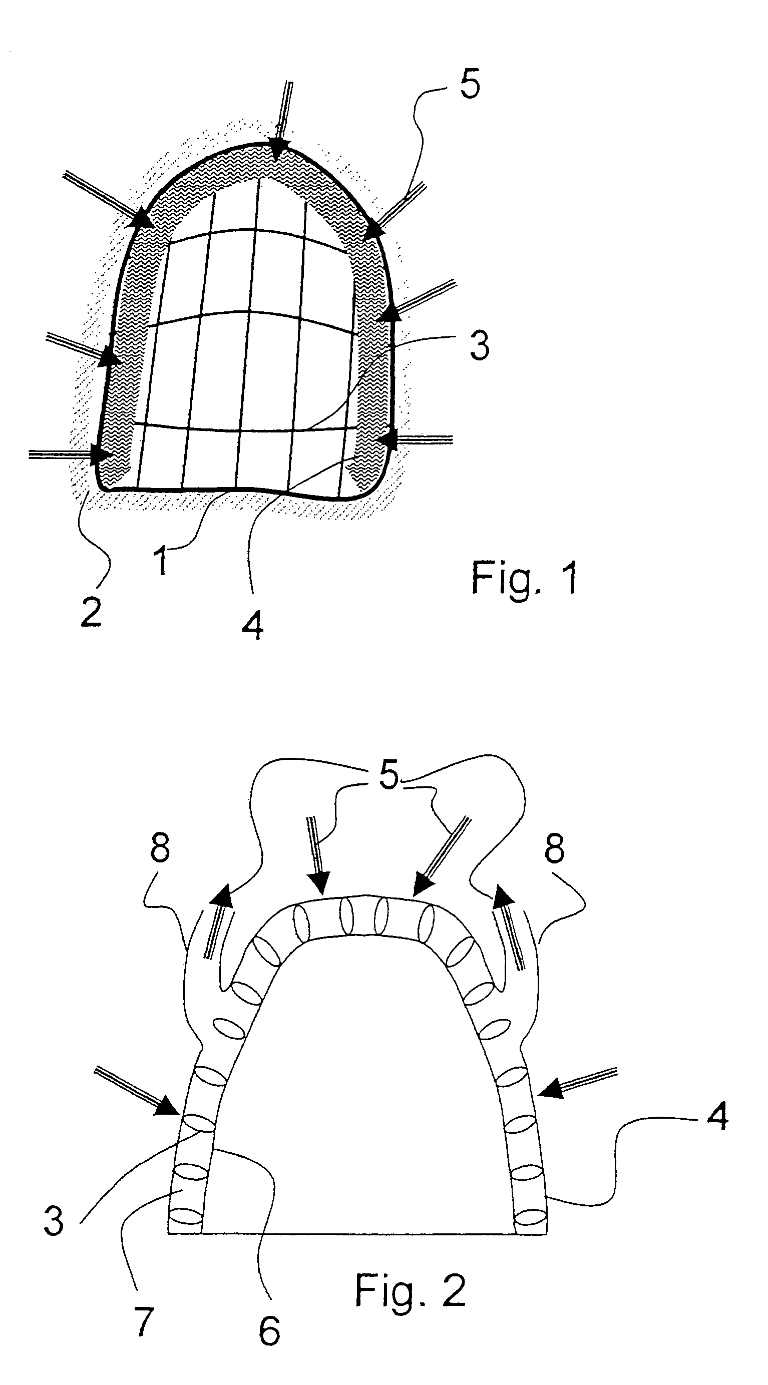
[0028]Referring to the drawings in particular, FIG. 1 shows a schematic view of the inner side of a mask body according to the present invention. A nasal CPAP mask has a fixed frame 1. This frame extends approximately in parallel to the contact surface of the mask on the face. On the patient side, this frame 1 carries a flexible, very soft seal 2, which is supported by the inner pressure of the mask. The frame 1 is provided with a grid-like skeleton as a shaping support frame 3, which approximately predetermines the three-dimensional shape of the mask. An air-permeable textile fabric, which also acts as a filter in the suction area 4 located close to the frame, is drawn over this skeleton on the outer side of the mask body. The ambient air is drawn in according to the present invention over the entire area 4, illustrated by the arrows 5. The rest of the surface of the mask body is available for the discharge of the expiratory breathing gases into the environment.

[0029]FIG. 2 shows a...


PUM


Abstract

A breathing mask for breathing support devices (10) to guide the breathing support gas to the patient. The mask includes a mask body including a material that is permeable to air at least in partial areas. A gas guiding structure is provided which can be connected to suction openings of the breathing support device (10). The gas guiding structure extends through the interior of the mask body. The gas guiding structure for the transport / delivery of gas is limited partially by air-permeable areas of the wall of the mask body, through which ambient air can be drawn in. The mask is characterized by high wear comfort and improved safety against accidental coverage of the suction areas.

Description

CROSS REFERENCE TO RELATED APPLICATIONS[0001]This application claims the benefit of priority under 35 U.S.C. § 119 of German Application 10 2004 055 433.1 filed Nov. 17, 2004, the entire contents of which are incorporated herein by reference.FIELD OF THE INVENTION[0002]The present invention pertains to a breathing mask with integrated suction area for breathing support devices to be worn by the patient.BACKGROUND OF THE INVENTION[0003]A possible application of such breathing masks is represented by so-called CPAP (continuous positive airway pressure) respirators. Patients who require breathing support for various reasons, for example, sleep apnea or COPD (chronic obstructive pulmonary disease), are frequently treated with such CPAP respirators. A settable overpressure for supporting the respiration is made available here to the patient. The supply is usually with constant pressure over the entire breathing cycle, the pressure set being made available for a breathing mask. These brea...

Claims


Application Information

Patent Timeline
Patent Type & Authority Patents(United States)
IPC IPC(8): A62B18/08A61M15/00A61M16/00A62B18/00A62B18/02A61M16/06A61M16/10A62B23/00A62D9/00
CPCA61M16/06A61M16/0683A61M16/0009A61M16/0616A61M16/10A61M16/107
Inventor KULLIK, GOTZHANSMANN, HANS-ULLRICH
Owner DRAGERWERK AG
Why Eureka
Try Eureka