Surface-stabilized semiconductor device

Inactive Publication Date: 2008-05-29
SANKEN ELECTRIC CO LTD
View PDF14 Cites 79 Cited by
  • Summary
  • Abstract
  • Description
  • Claims
  • Application Information

AI Technical Summary

Benefits of technology

[0009]It is among the objects of this invention to stabilize the surface of semiconductor d

Problems solved by technology

The semiconductor surface will become electrically unstable, and current leakage will occur between the electrodes, if charge carriers (e.g., electrons) are captured there.
All these conventional methods have their own strengths, but weaknesses do appear particularly when they are applied to nitride or like compound semiconductors because, unlike silicon semiconductors, compound semiconductors have many crystal defects and interface states.
Another problem that manifests itself in relation to the electrification of the semiconductor surface is the so-called current collapse which takes place in a high electron mobility transistor (HEMT).
The electron density of the two-dimensional electron

Method used


Image

  • Surface-stabilized semiconductor device
  • Surface-stabilized semiconductor device
  • Surface-stabilized semiconductor device

Examples


embodiment

of FIG. 2

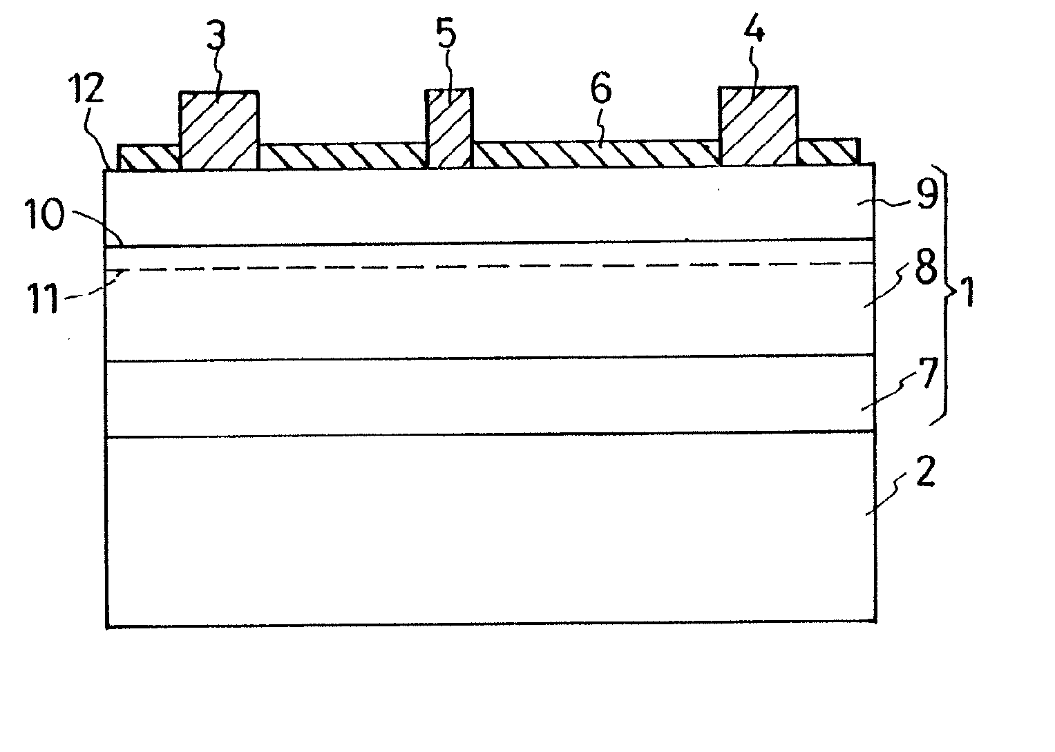
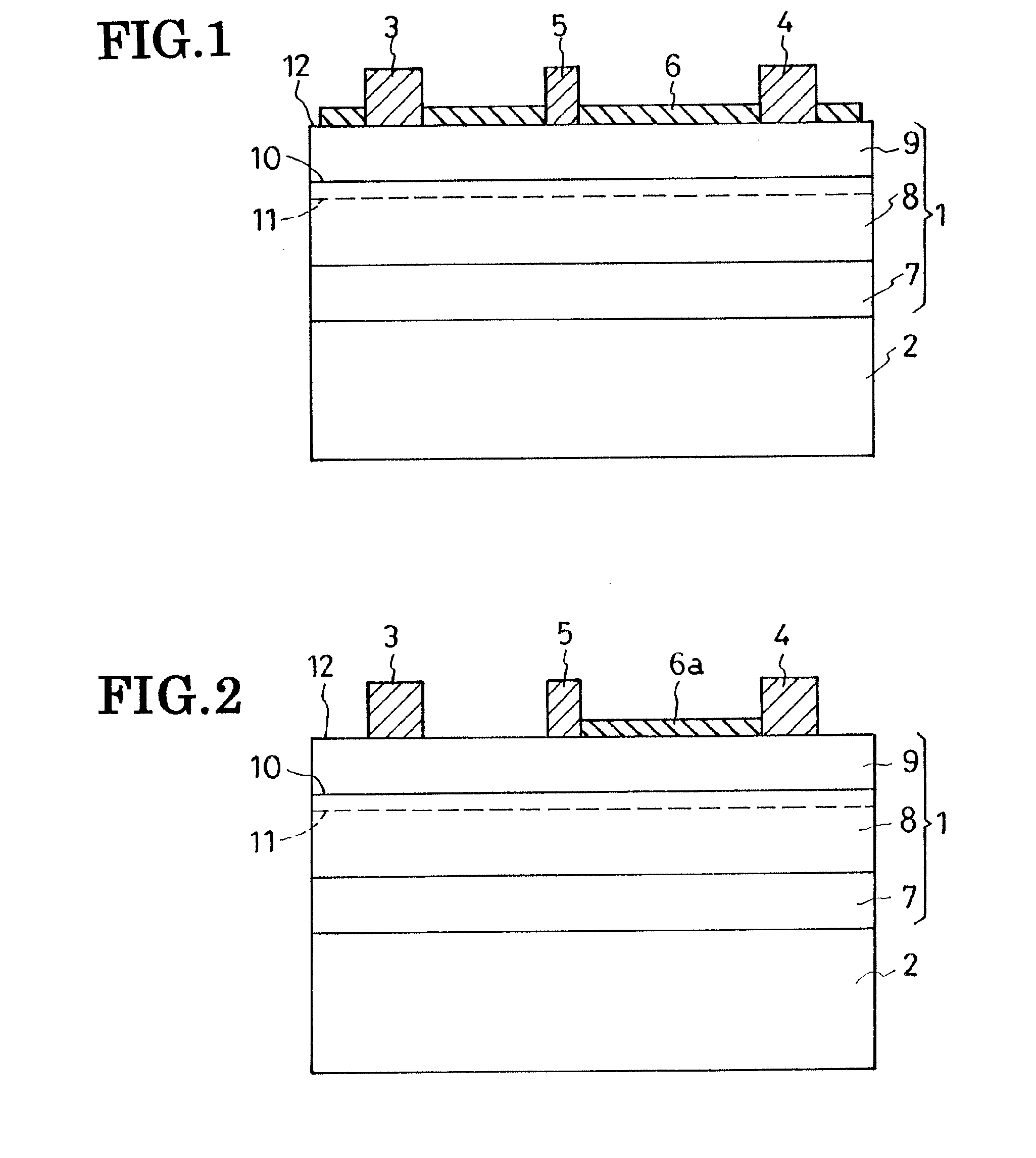
[0046]The HEMT seen here is of the same construction as that of FIG. 1 except for a p-type organic semiconductor overlay 6a which covers all of that part of the major surface 12 of the main semiconductor region 1 which lies between drain 4 and gate 5. The limited coverage of the semiconductor surface 12 by the overlay 6a is effective for restriction of the lessening of electrons, and consequent current collapse, in the underlying part of the two-dimensional electron gas layer 11.

Embodiment of FIG. 3

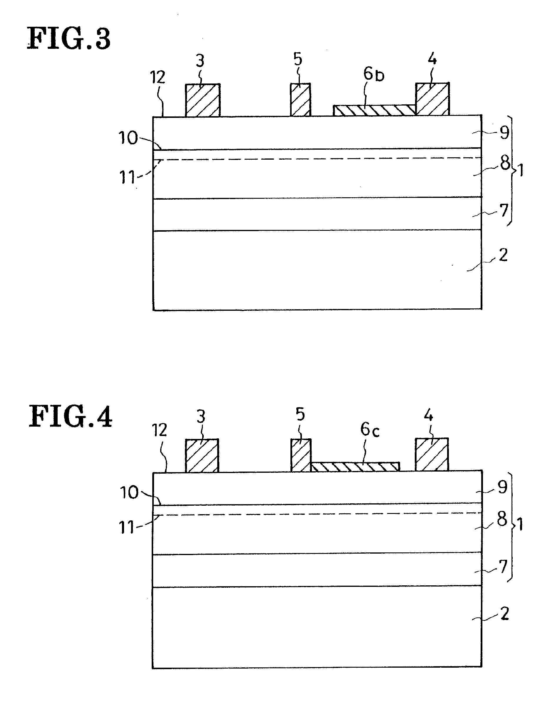
[0047]This embodiment differs from that of FIG. 2 only in an organic semiconductor overlay 6b which covers only part of that part of the major surface 12 of the main semiconductor region 1 which lies between drain 4 and gate 5. A spacing exists between gate 5 and overlay 6b. This overlay 6b is nearly as effective as its FIG. 2 counterpart 6a.

Embodiment of FIG. 4

[0048]The organic semiconductor overlay 6c depicted here is similar in size and positioning to its FIG. 3 counterpart 6b...


PUM


Abstract

A high electron mobility transistor is disclosed which has a main semiconductor region formed on a silicon substrate. The main semiconductor region is a lamination of a buffer layer on the substrate, an electron transit layer on the buffer layer, and an electron supply layer on the electron transit layer. A source, drain, and gate overlie the electron supply layer. Also formed on the electron supply layer is a surface-stabilizing organic semiconductor overlay which is of p conductivity type in contrast to the n type of the electron supply layer.

Description

CROSS REFERENCE TO RELATED APPLICATIONS[0001]This is a continuation of Application PCT / JP2006 / 311214, filed Jun. 5, 2006, which claims priority to Japanese Patent Application No. 2005-204966 filed Jul. 13, 2005.BACKGROUND OF THE INVENTION[0002]This invention relates to semiconductor devices such as field-effect transistors (FETs), Schottky-barrier diodes (SBDs), and pn-junction diodes. More particularly, the invention deals with the surface stabilization of such semiconductor devices.[0003]Crystalline semiconductor regions of semiconductor devices have unique interface states at their surfaces. The semiconductor surface will become electrically unstable, and current leakage will occur between the electrodes, if charge carriers (e.g., electrons) are captured there. Current leakage should be reduced to a minimum by any means. It is customary in the semiconductor industry to assess the voltage-withstanding capability of a semiconductor device in terms of current leakage. The more prone...

Claims


Application Information

Patent Timeline
IPC IPC(8): H01L51/05
CPCH01L23/293H01L29/2003H01L29/402H01L29/405H01L2924/12044H01L29/7787H01L29/78H01L29/8611H01L29/872H01L29/475H01L2924/0002
Inventor OTSUKA, KOJIMACHIDA, OSAMUMUROFUSHI, HITOSHI
Owner SANKEN ELECTRIC CO LTD
Why Eureka
Try Eureka