Boattail plates with non-rectangular geometries for reducing aerodynamic base drag of a bluff body in ground effect

a boattail plate and aerodynamic base drag technology, which is applied in the direction of roofs, transportation and packaging, vehicle arrangements, etc., can solve the problems of increasing fuel costs correspondingly

Inactive Publication Date: 2006-03-07
LAWRENCE LIVERMORE NAT SECURITY LLC
View PDF14 Cites 62 Cited by
  • Summary
  • Abstract
  • Description
  • Claims
  • Application Information

AI Technical Summary

Benefits of technology

[0010]Another aspect of the present invention include, in a bluff body land-based vehicle having a leading end, a trailing end, a top surface, opposing first and second side surfaces, and a substantially flat base surface at the trailing end substantially normal to a longitudinal centerline of the bluff body, the improvement comprising: means located alongside at least one of the top surface and first and second side surfaces for generating, in a flowstream substantially parallel to the longitudinal centerline, a pair of counter-rotating vortices which confluence together downstream in the wake of the vehicle in a direction orthogonal to the flowstream such that the confluence induces the flowstream passing over the top surface to turn down and around behind the trailing end to raise the pressure on the base surface and reduce the aerodynamic base drag.

Problems solved by technology

As the aerodynamic drag experienced by a vehicle increases, the fuel costs also correspondingly increase due to the greater energy required to overcome the drag.

Method used


Image

  • Boattail plates with non-rectangular geometries for reducing aerodynamic base drag of a bluff body in ground effect
  • Boattail plates with non-rectangular geometries for reducing aerodynamic base drag of a bluff body in ground effect
  • Boattail plates with non-rectangular geometries for reducing aerodynamic base drag of a bluff body in ground effect

Examples


Embodiment Construction

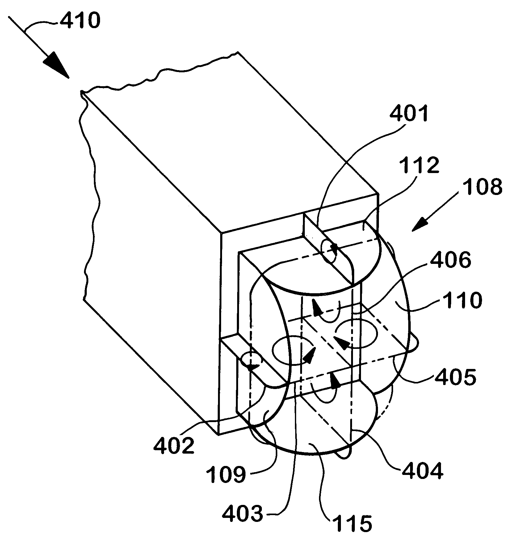
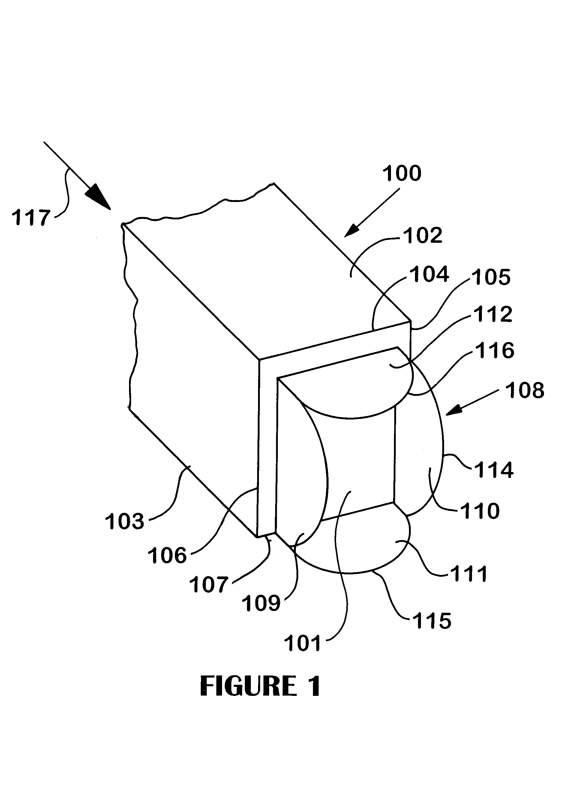
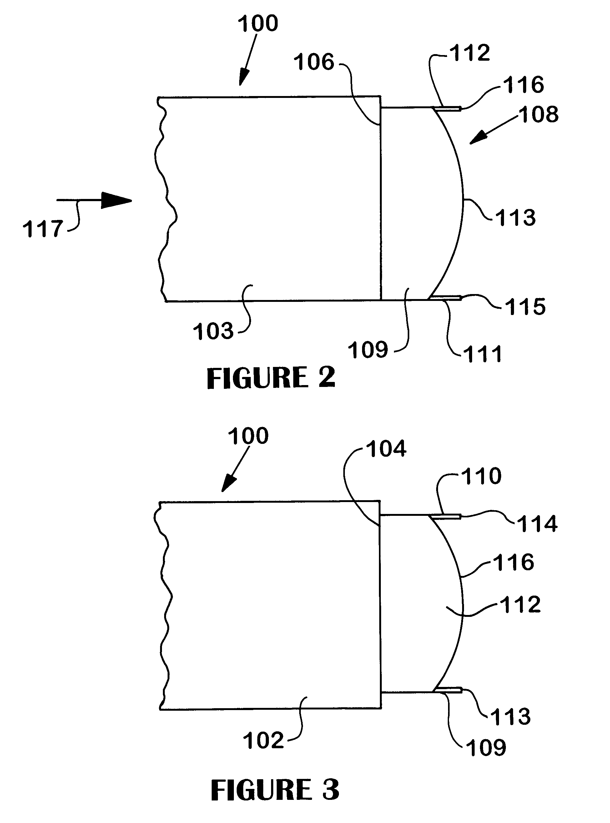
[0019]The present invention is directed to an aerodynamic base drag reduction apparatus and method for use with a bluff body or bluff body vehicle, such as for example a tractor-trailer or other land-based vehicle. “Bluff bodies” are one of two types of fluid-dynamic shapes (the other being “streamlined bodies”) and can be generally characterized by the presence of a sizeable recirculation zone in the wake of the bluff body. Thus, bluff bodies are characteristically blunt-ended, non-streamlined moving bodies having a relatively large base surface at a trailing end which causes the large recirculation zone in the wake of the bluff body to produce the base drag. And the base surface of a bluff body vehicle is typically of a type oriented substantially normal to the flowstream, as is commonly seen in tractor-trailer arrangements. This arrangement creates a sharp separation of the flow stream at the edge of base surface and thereby lowers the pressure on the base surface to produce the ...


PUM


Abstract

An apparatus for reducing the aerodynamic base drag of a bluff body having a leading end, a trailing end, a top surface, opposing left and right side surfaces, and a base surface at the trailing end substantially normal to a longitudinal centerline of the bluff body, with the base surface joined (1) to the left side surface at a left trailing edge, (2) to the right side surface at a right trailing edge, and (3) to the top surface at a top trailing edge. The apparatus includes left and right vertical boattail plates which are orthogonally attached to the base surface of the bluff body and inwardly offset from the left and right trailing edges, respectively. This produces left and right vertical channels which generate, in a flowstream substantially parallel to the longitudinal centerline, respective left and right vertically-aligned vortical structures, with the left and right vertical boattail plates each having a plate width defined by a rear edge of the plate spaced from the base surface. Each plate also has a peak plate width at a location between top and bottom ends of the plate corresponding to a peak vortex of the respective vertically-aligned vortical structures.

Description

I. CLAIM OF PRIORITY IN PROVISIONAL APPLICATION[0001]This application claims priority in provisional application filed on Sep. 20, 2002, entitled “Drag Reduction of a Bluff Body in Ground Effect Through the Use of Counter-Rotating Vortex Pairs” Ser. No. 60 / 412417, and provisional application filed on, May 30, 2003 entitled “Drag Reduction of a Bluff Body in Ground Effect Through the Use of Wedge-Shaped Boattail Plates” Ser. No. 60 / 475212 both by Jason M. Ortega et al.[0002]The United States Government has rights in this invention pursuant to Contract No. W-7405-ENG-48 between the United States Department of Energy and the University of California for the operation of Lawrence Livermore National Laboratory.II. FIELD OF THE INVENTION[0003]The present invention relates to aerodynamic drag reduction devices and methods, and more particularly to an aerodynamic base drag reduction apparatus and method for bluff bodies using boattail plates having non-rectangular geometries for reducing ae...

Claims


Application Information

Patent Timeline
Patent Type & Authority Patents(United States)
IPC IPC(8): B62D35/00
CPCB62D35/004
Inventor ORTEGA, JASON M.SABARI, KAMBIZ
Owner LAWRENCE LIVERMORE NAT SECURITY LLC
Why Eureka
Try Eureka