Ejection controlling device for inkjet printer and controlling method thereof with optimal density

a technology of inkjet printer and control device, which is applied in the direction of printing, other printing apparatus, etc., can solve problems such as degrading printing quality

Inactive Publication Date: 2006-03-07
S PRINTING SOLUTION CO LTD
View PDF2 Cites 11 Cited by
  • Summary
  • Abstract
  • Description
  • Claims
  • Application Information

AI Technical Summary

Benefits of technology

[0017]The controlling part may compare the densities of the patterns in ascending order to determine, as an optimal pulse width, the width of the pulse corresponding to the pattern which has the highest density that is larger, by a predetermined difference, than the density of the previous pattern.
[0018]The controlling part may control the driving part to perform the printing operation according to the width of the pulse stored in the memory upon inputting a printing command.

Problems solved by technology

These variations prevent a uniform amount of ink ejection, thereby degrading the printing quality.

Method used


Image

  • Ejection controlling device for inkjet printer and controlling method thereof with optimal density
  • Ejection controlling device for inkjet printer and controlling method thereof with optimal density
  • Ejection controlling device for inkjet printer and controlling method thereof with optimal density

Examples


Embodiment Construction

[0025]Reference will now be made in detail to the present preferred embodiments of the present invention, examples of which are illustrated in the accompanying drawings, wherein like reference numerals refer to the like elements throughout. The embodiments are described below in order to explain the present invention by referring to the figures.

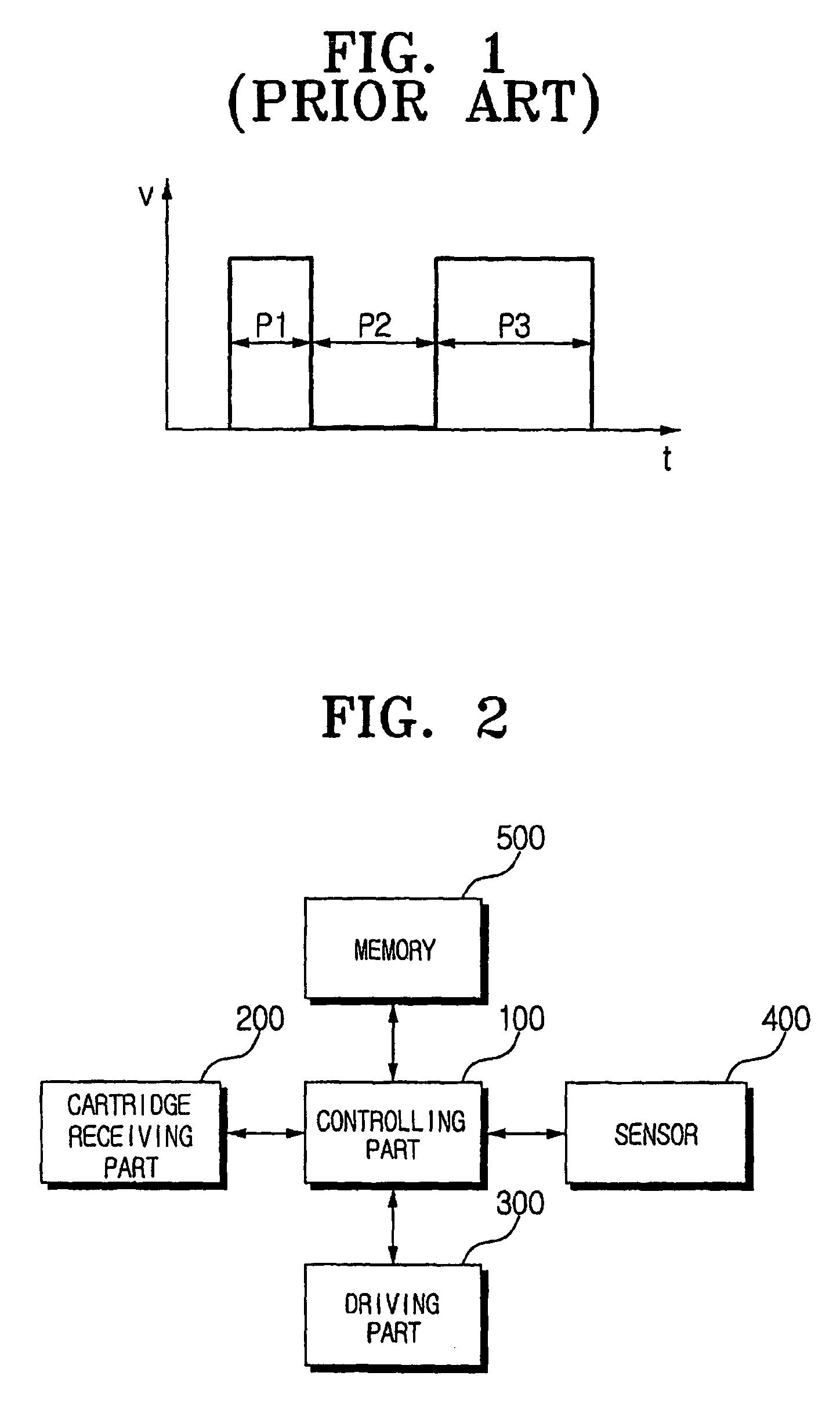
[0026]FIG. 2 is a block diagram of a controlling device for an inkjet printer according to an embodiment of the invention. As shown in FIG. 2, the controlling device comprises a cartridge receiving part 200 receiving an ink cartridge, a driving part 300 driving an ink ejection heater to perform a printing operation, a sensor 400 sensing printing densities of printed patterns, a controlling part 100 setting widths of pulses to be inputted to the ink ejection heater, and controlling the controlling device for the inkjet printer overall, and a memory 500 for storing an optimal width of a pulse determined by the controlling part 100.

[0027]The car...


PUM


Abstract

An ejection controlling device for an inkjet printer and a controlling method thereof includes determining whether an ink cartridge is installed in the inkjet printer, printing patterns in order by driving an ink ejection heater with an array of predetermined pulses with widths that vary in sequential order in response to the ink cartridge being connected to the inkjet printer, detecting printing densities of the printed patterns; determining the pattern with an optimal density among the printing densities, and storing the width of the pulse corresponding to the pattern with the optimal density as an optimal pulse width.

Description

CROSS-REFERENCE TO RELATED APPLICATIONS[0001]This application claims the benefit of Korean Application No. 2002-67624, filed Nov. 2, 2002, in the Korean Intellectual Property Office, the disclosure of which is incorporated herein by reference.BACKGROUND OF THE INVENTION[0002]1. Field of the Invention[0003]The present invention relates to an inkjet printer, and, more particularly, to an ejection controlling device for an inkjet printer, and a controlling method thereof, that is capable of adjusting an amount of ejected ink properly.[0004]2. Description of the Related Art[0005]A general inkjet printer drives an ink ejection heater for ejecting ink in an ink cartridge to print onto a printing medium. The inkjet printer comprises a heater driving control unit for controlling a width or waveform of a driving pulse to drive the ink ejection heater according to a temperature of an ink cartridge head.[0006]FIG. 1 is a graph showing a driving pulse of a conventional ink injection heater. P1 ...

Claims


Application Information

Patent Timeline
Patent Type & Authority Patents(United States)
IPC IPC(8): B41J29/393B41J2/05
CPCB41J2/04528B41J2/04558B41J2/0458B41J29/393B41J2/04593B41J2/04598B41J2/04591
Inventor JU, YOUNG-BOKIM, DAE-HYEOK
Owner S PRINTING SOLUTION CO LTD
Why Eureka
Try Eureka