Method and system for controlling the temperature of components

a technology of temperature control and components, applied in the direction of lighting and heating apparatus, heating types, instruments, etc., can solve the problems of insufficient energy efficiency, uneven heat distribution, and inability to precisely set individual strands or heating circuits, so as to achieve uniform energy delivery to components, reduce the effect of substantial disadvantages and reduce the effect of significant disadvantages

Active Publication Date: 2013-08-29
OBLAMATIK AG
View PDF54 Cites 19 Cited by
  • Summary
  • Abstract
  • Description
  • Claims
  • Application Information

AI Technical Summary

Benefits of technology

[0005]It is therefore the object of the present invention to propose a temperature-control method and a temperature-control system, which is capable of carrying out this method, for heating or cooling a component, which eliminate or at least minimize the substantial disadvantages known from the prior art. It is preferable in particular for this temperature-control method to allow significantly more uniform energy delivery to components or significantly more uniform energy absorption from components and therefore to increase the comfort and the energy efficiency.
[0036]Because the regulation is actively performed, the supply temperature can be kept low and therefore the heating costs can be minimized;
[0037]The influence of interfering variables (heating sources such as open fires or cooling sources such as open windows) can be minimized: Opening a window does not generate an additional heating requirement, for example, sunny weather even reduces the heating requirement; for example, separate window switches are not required in hotels;
[0038]Through the achievable uniform heat distribution, the consumer consistently enjoys higher comfort (even in the event of partial mud blockage);

Problems solved by technology

In spite of experience and the application of the greatest care, only imprecise setting of the individual strands or heating circuits is therefore possible, however.
Uneven heat distribution, on the one hand, or insufficient energy efficiency, on the other hand, results therefrom.
Furthermore, in the case of renovations, the theoretically ascertained manipulated variables are not available and can only be ascertained with great effort.
A further problem is represented by inaccurate room thermostats, which often exert a simple on / off function on such a floor heater.
Although there are approaches for more precisely ascertaining the energy consumption of heating systems (cf., e.g., DE 44 17 941 A1), up to this point concepts which could successfully remedy the substantial disadvantages of the above-described prior art have been lacking.

Method used


Image

  • Method and system for controlling the temperature of components
  • Method and system for controlling the temperature of components
  • Method and system for controlling the temperature of components

Examples


first embodiment

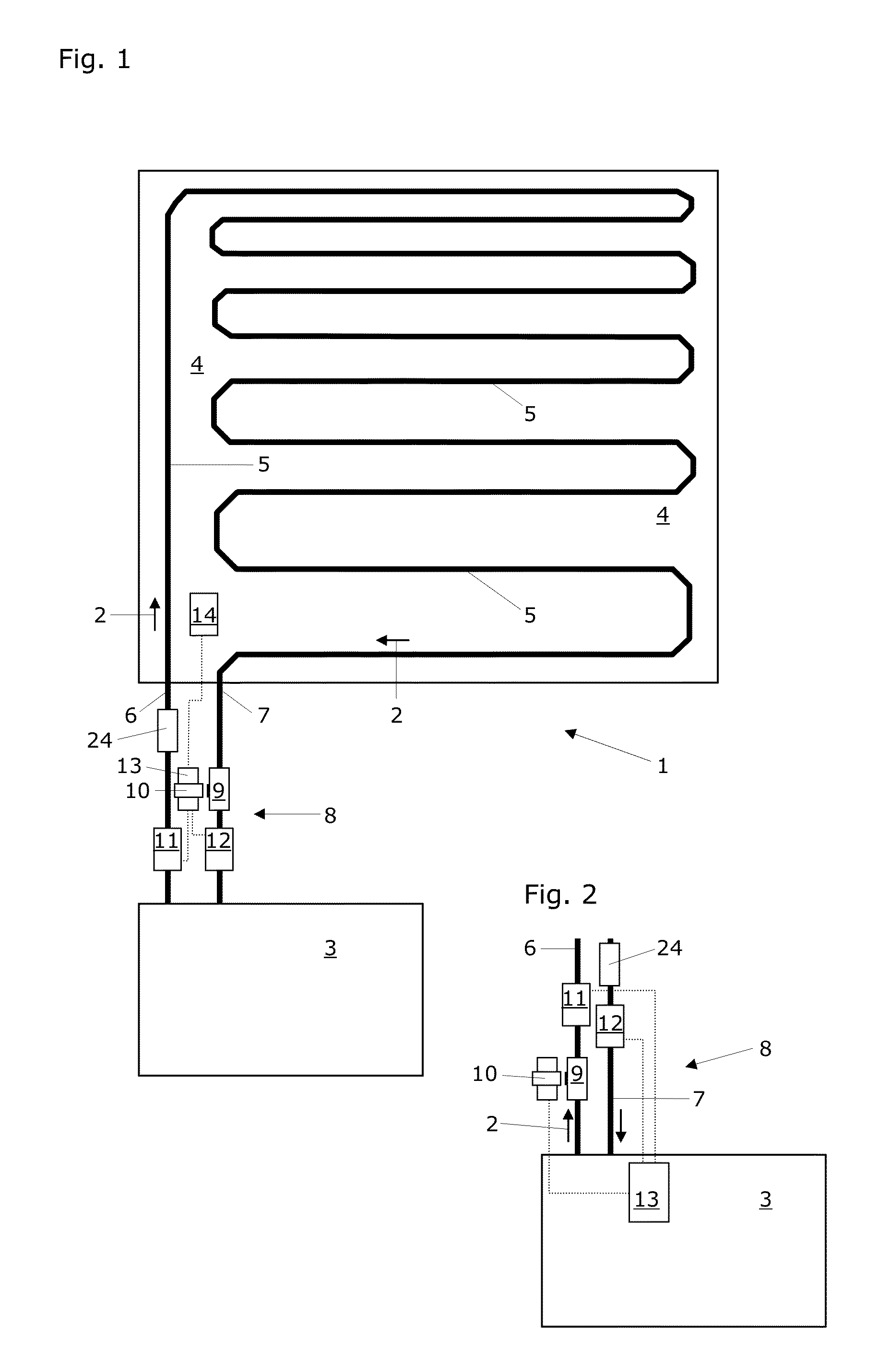
[0054]FIG. 1 shows a schematic top view of a simpler temperature-control system according to a This temperature-control system is capable of carrying out the method according to the invention for the controlling the temperature of a component. This simpler temperature-control system 1 for carrying out the temperature-control method according to the invention comprises a temperature-control device 3, which is implemented to heat or cool a temperature-control fluid 2. This simpler temperature-control system 1 additionally comprises a temperature-control arrangement 5, which is implemented to conduct the temperature-control fluid 2 through a component 4 to be controlled in temperature (in the exemplary form of a meandering pipe laid in the component 4).

[0055]This simpler temperature-control system 1 additionally comprises a supply line 6, via which the temperature-control device 3 is connected to the temperature-control arrangement 5 to supply the temperature-control fluid 2, and a re...

second embodiment

[0063]Comparably thereto, FIG. 2 shows a schematic partial top view of the controller of a simpler temperature-control system in which the sensors for the supply temperature 11 and the return temperature 12 are arranged near the valve 9, which is inserted into the supply line 6 here. The actuator 10 is again arranged directly at the valve 9. The regulator 13 is located at a practically arbitrary distance from the above-mentioned components of the controller 8 and is located near the temperature-control device 3 or is even integrated in the latter. The regulator 13 is electrically connected to the supply temperature sensor 11 and to the return temperature sensor 12 and also to the actuator 10, which is illustrated here by dotted lines. The shutoff valve 24 is inserted into the return line 7 here. The controller 8 is therefore distributed onto a region outside the component 4 and a region at or inside the temperature-control device 3.

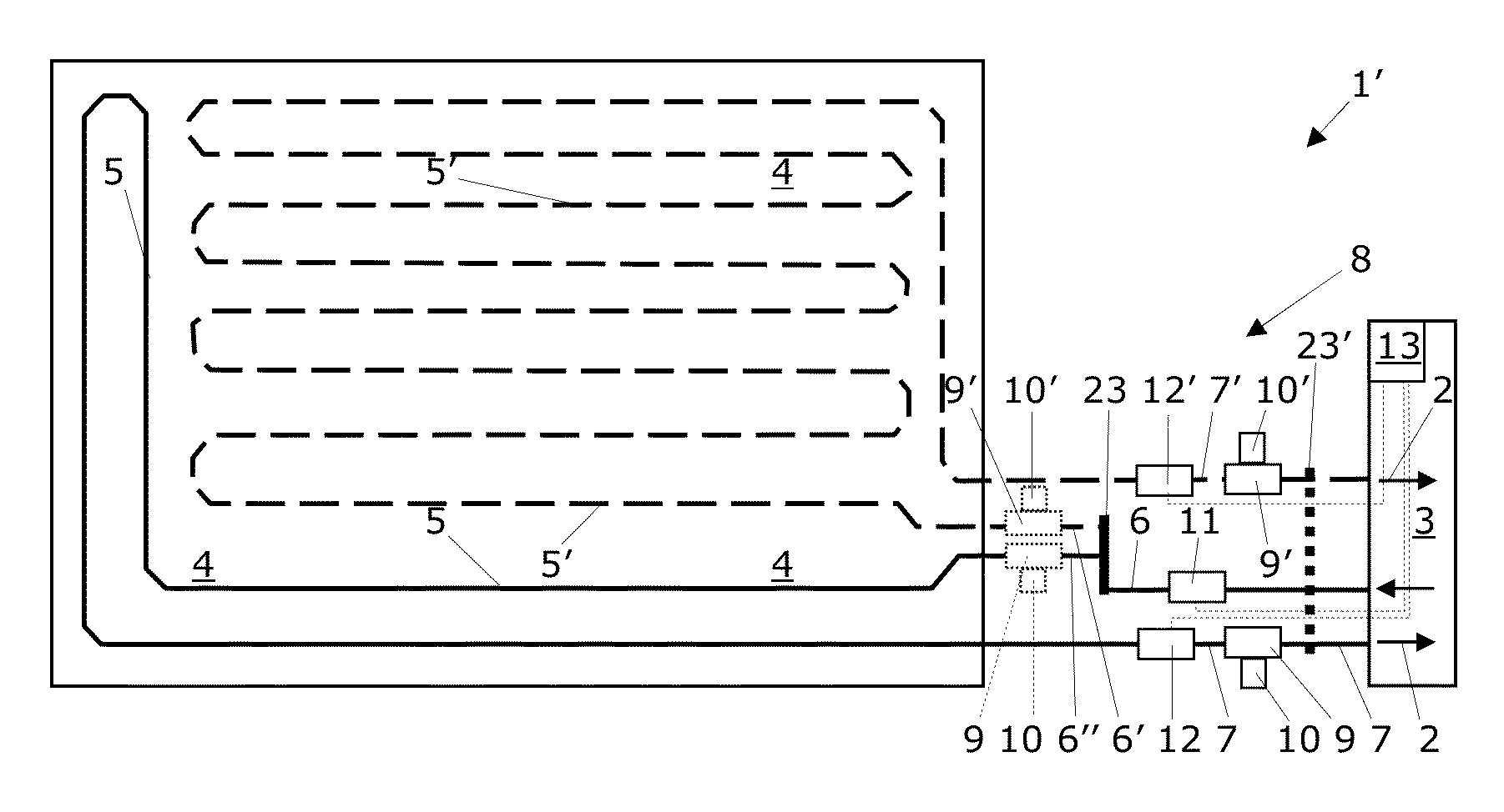
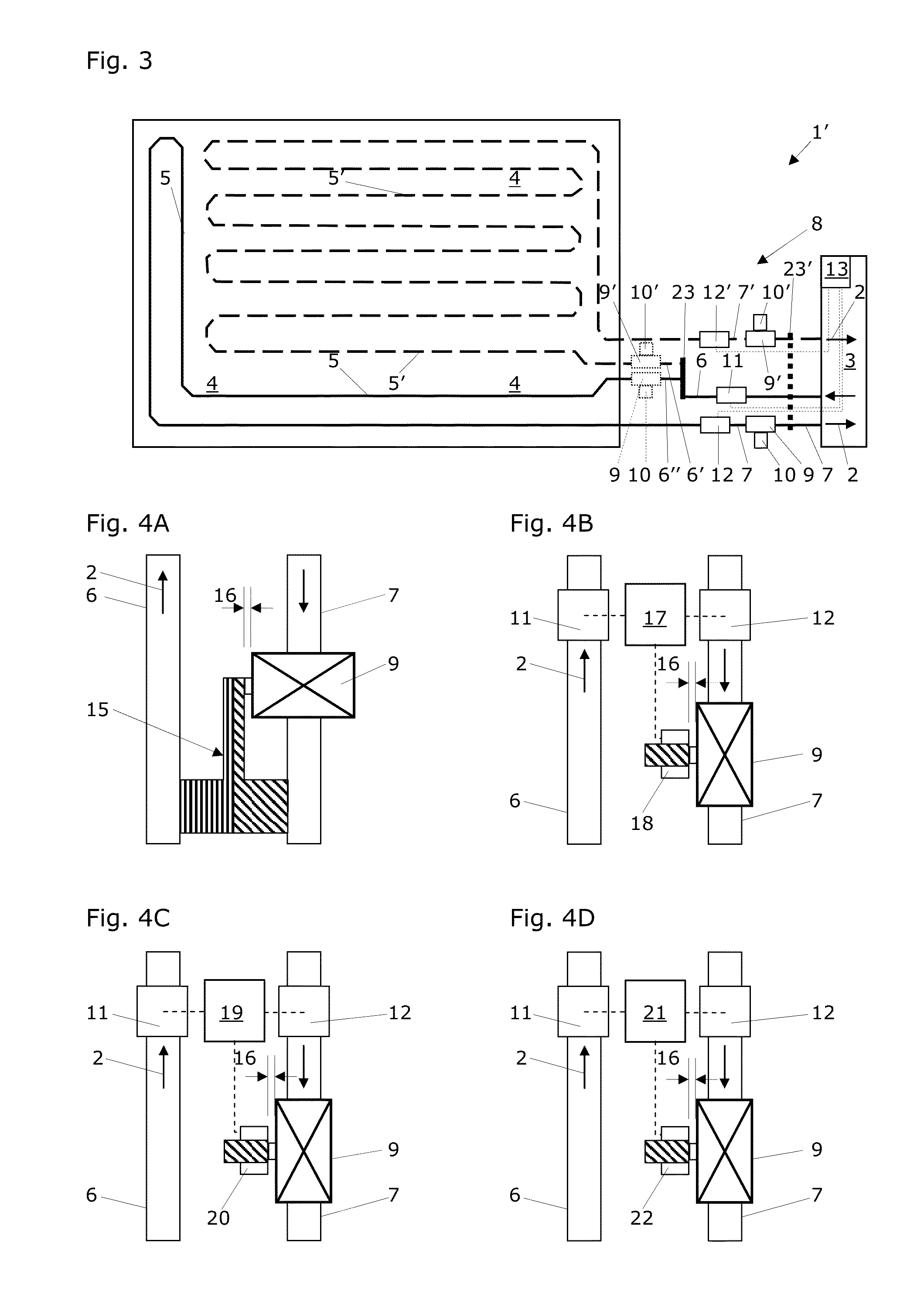
[0064]FIG. 3 shows a schematic top view of a more ...


PUM


Abstract

Temperature-control system used for heating or cooling in a method for controlling temperature of a component includes connected temperature-control device, temperature-control arrangement, supply line, and return line. The system additionally has a controller having a valve, an actuator, a supply temperature sensor, and a return temperature sensor. A temperature difference between the supply temperature and the return temperature of a fluid circulating in the system is registered using the supply temperature sensor and the return temperature sensor and also a regulator. Proceeding from this temperature difference, the regulator causes the actuator to set a degree of opening of the valve so the temperature difference is in a selected value range. The valve always has a minimal degree of opening in the open state.

Description

RELATED PATENT APPLICATIONS[0001]This patent application claims priority of the Swiss Patent Application No. CH 00266 / 12 of Feb. 29, 2012, the entire disclosure of which is herein incorporated by explicit reference for any purpose.RELATED FIELD OF TECHNOLOGY[0002]The invention relates to a temperature-control method for temperature control, i.e., for heating or cooling a component. Such components are, for example, a floor, a wall, or a ceiling of a living or working space; they can also be freestanding heating or cooling walls, however. A temperature-control system capable of carrying out this temperature-control method typically comprises a temperature-control device, a temperature-control arrangement, a supply line, and a return line, which are all connected to one another. This temperature-control system additionally comprises a control and regulating unit having an actuator, a supply temperature sensor, and a return temperature sensor.RELATED PRIOR ART[0003]In the temperature-c...

Claims


Application Information

Patent Timeline
Patent Type & Authority Applications(United States)
IPC IPC(8): F24D19/10F24D3/14F24F5/00F24F11/02
CPCF24F3/06F24F2011/0082F24D19/1015G05D23/1927F24D3/14F24F5/0092F24D3/12F24F11/022G05D23/08G05D23/1931F24F11/84F24F11/72F24D2220/0264Y02B30/00
Inventor LANG, EDOOBRIST, ROLAND
Owner OBLAMATIK AG
Why Eureka
Try Eureka