Uniform light spot surface scanning device of laser cleaning machine

A laser cleaning and surface scanning technology, used in optics, optical components, instruments, etc., can solve problems such as leakage cleaning or over cleaning, difficult correction of optical systems and mechanical mechanisms, and distortion of spot position, achieving small diameter and laser cleaning. The effect of increased speed and low optical power loss

Active Publication Date: 2014-07-30
BEIJING INST OF AEROSPACE CONTROL DEVICES
View PDF3 Cites 18 Cited by
  • Summary
  • Abstract
  • Description
  • Claims
  • Application Information

AI Technical Summary

Problems solved by technology

The defect of the first linear scanning method is that when the moving speed of the worktable is uneven, it is easy to cause leakage or over-cleaning.
The defect of the second and third planar scanning methods is that the spot position on the target plane is distorted, and there is no linear correspondence, so it is difficult to correct only by the optical system and mechanical mechanism
At the same time, these three beam scanning methods all have control circuits, and the control, installation, complexity and reliability of the circuits need to be considered
And the galvanometer system is not suitable for places with harsh external environments (vibration, large changes in temperature and humidity)

Method used


Image

  • Uniform light spot surface scanning device of laser cleaning machine
  • Uniform light spot surface scanning device of laser cleaning machine
  • Uniform light spot surface scanning device of laser cleaning machine

Examples


Embodiment

[0040] A specific example of the present invention is described below in conjunction with accompanying drawing:

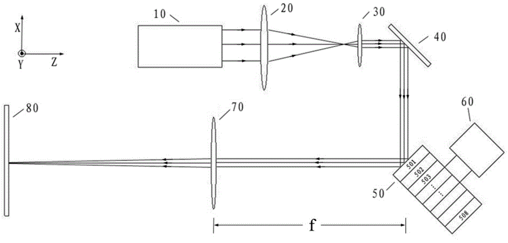
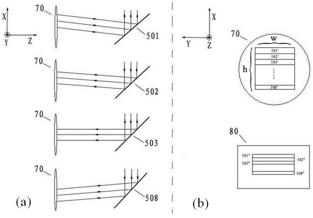
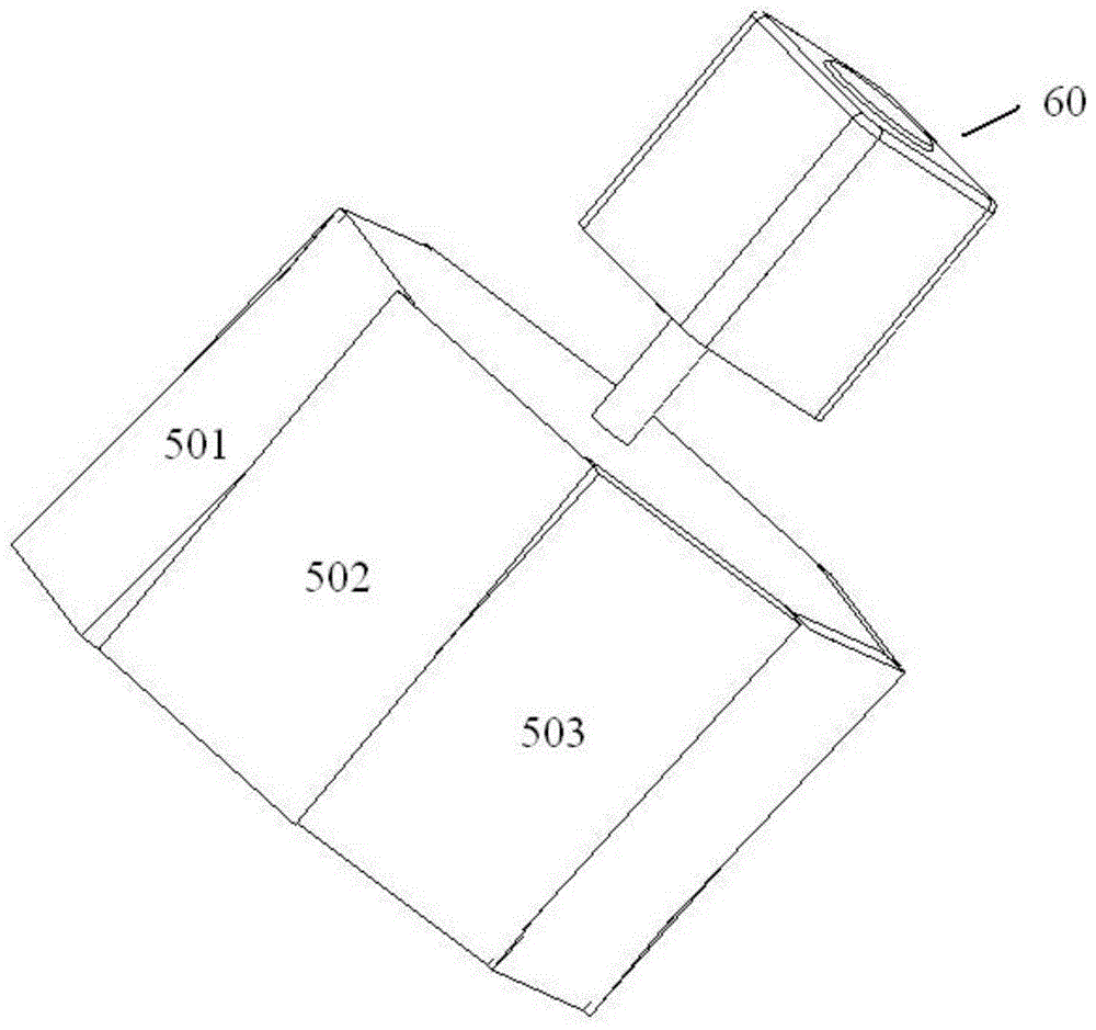
[0041] This example is designed for an infrared laser with a circular spot shape (diameter 8mm), a Gaussian distribution of light energy, and a center wavelength of 1064nm. It is suitable for laser cleaning and laser surface treatment. This example is composed of a laser output module 10 , an aspheric lens 20 , an aspheric lens 30 , a reflector 40 , a progressive rotating polygonal mirror 50 , a driving motor 60 and a collimating focusing lens 70 .

[0042] The components and features contained in the device are: the working laser source is fiber laser, YAG laser or CO2 laser, the laser output module 10 emits continuous or pulsed laser, the energy is non-uniformly distributed (typically Gaussian), and the laser wavelength range is 0.532 μm ~10.64μm, the output power is less than 1000W; the material of the aspheric lens 20 and 30 is quartz, CaF or ZnSe, the surface ...


PUM


Abstract

A uniform light spot surface scanning device of a laser cleaning machine comprises a laser output module (10), a gauss-flat top system, a gradually-changing rotating polygonal mirror (50), a drive motor (60) and a collimation focusing lens (70). The gauss-flat top system redistributes the energy of a gaussian laser beam emitted by the laser output module (10) and compresses the diameter of the laser beam at the same time, so that a laser beam with uniform energy is formed; the laser beam irradiates the gradually-changing rotating polygonal mirror (50); the gradually-changing rotating polygonal mirror (50) is driven by the drive motor (60) to rotate so as to make the laser beam form a space angle scanning beam; the space angle scanning beam is refracted by the collimation focusing lens (70) and then forms surface light spots on an object (80) to be cleaned.

Description

technical field [0001] The invention relates to a uniform spot surface scanning method and device for a laser cleaning machine. It is an optical system that transforms and shapes the laser beam with uneven energy distribution and spot-like spots into a laser spot with uniform energy distribution and surface scanning. Mainly used in laser cleaning or other laser surface treatment fields. Background technique [0002] Laser cleaning technology uses high-power density laser to directly irradiate the surface of the object, so that the coating, rust and oil stains attached to the surface evaporate, ablate or peel off instantly. In most cases, the output of the laser is a circular parallel beam with a Gaussian energy distribution. When the current laser cleaning machine scans, it usually uses a collimating focusing lens to directly focus the beam, so the energy of the laser spot on the surface of the object to be cleaned is also Gaussian, which makes the energy of the center of ...

Claims


Application Information

Patent Timeline
Patent Type & Authority Applications(China)
IPC IPC(8): G02B27/09G02B26/12
Inventor 王学锋刘佳于文鹏王军龙于淼
Owner BEIJING INST OF AEROSPACE CONTROL DEVICES
Why Eureka
Try Eureka