Substrate for a thermal ink jet printhead, a colour printhead in particular, and ink jet printhead incorporation this substrate

a technology of thermal ink jet printheads and substrates, which is applied in the field of substrates, can solve the problems of affecting the production cycle, the structure and configuration of substrates are more complex, and the relative drive circuit is particularly critical, so as to achieve low defect rate, less prone to cracking, and high robust structure

Inactive Publication Date: 2006-03-07
OLIVETTI I JET
View PDF7 Cites 4 Cited by
  • Summary
  • Abstract
  • Description
  • Claims
  • Application Information

AI Technical Summary

Benefits of technology

[0039]Another object of the invention is to produce a substrate, intended for the manufacture of ink jet printheads, which has an extremely low defect rate during the relative manufacturing cycle, and which in particular has a highly robust structure that is less liable to cracking, in the zone of separation of the slots for the flow of ink, than the substrates known today.
[0040]A further object is to produce an ink jet printhead, in particular color type, having a manufacturing process in which both the operation of separating and of hermetical sealing between the different hydraulic circuits intended for conveying the different color inks can be carried out with a higher degree of efficiency and quality with respect to the known heads having the ducting slots aligned in a row along the lengthwise direction.

Problems solved by technology

Clearly the greater the number of nozzles used, the greater the number of corresponding ejection actuators, and therefore the more complex the structure and configuration of the substrate integrating the ejection actuators and relative drive circuits.
Unfortunately, it often happens that the configuration adopted for the known substrates has characteristics which, at least potentially, could render the substrate manufacturing cycle particularly critical, and in particular foster the occurrence of defects during the cycle.
For example, a configuration comprising a plurality of slots aligned exactly with one another, in the lengthwise direction, tends to render the substrate particularly fragile local to the zones of separation between the slots.
On the other hand, excessively reducing the zones of separation between the slots renders especially critical and delicate, and therefore easily subject to defects, the operation of hermetical sealing, local to these zones, between the hydraulic circuits intended for conveying the different color inks, i.e. that sealing operation the object of which is to avoid the various hydraulic circuits of the printhead, each corresponding to a given slot and to a given color ink, coming into communication with one another.
Thus a configuration of a substrate in which the slots are aligned longitudinally is clearly not capable of optimally satisfying the conflicting requirements outlined above.
This configuration, though it avoids having the slots arranged in a row lengthwise, is not entirely free of drawbacks, and for instance has the terminals in not necessarily the most convenient or optimal configuration, for the purpose for instance of assembling the various parts comprising the printhead that the substrate is built into.

Method used


Image

  • Substrate for a thermal ink jet printhead, a colour printhead in particular, and ink jet printhead incorporation this substrate
  • Substrate for a thermal ink jet printhead, a colour printhead in particular, and ink jet printhead incorporation this substrate
  • Substrate for a thermal ink jet printhead, a colour printhead in particular, and ink jet printhead incorporation this substrate

Examples


second embodiment

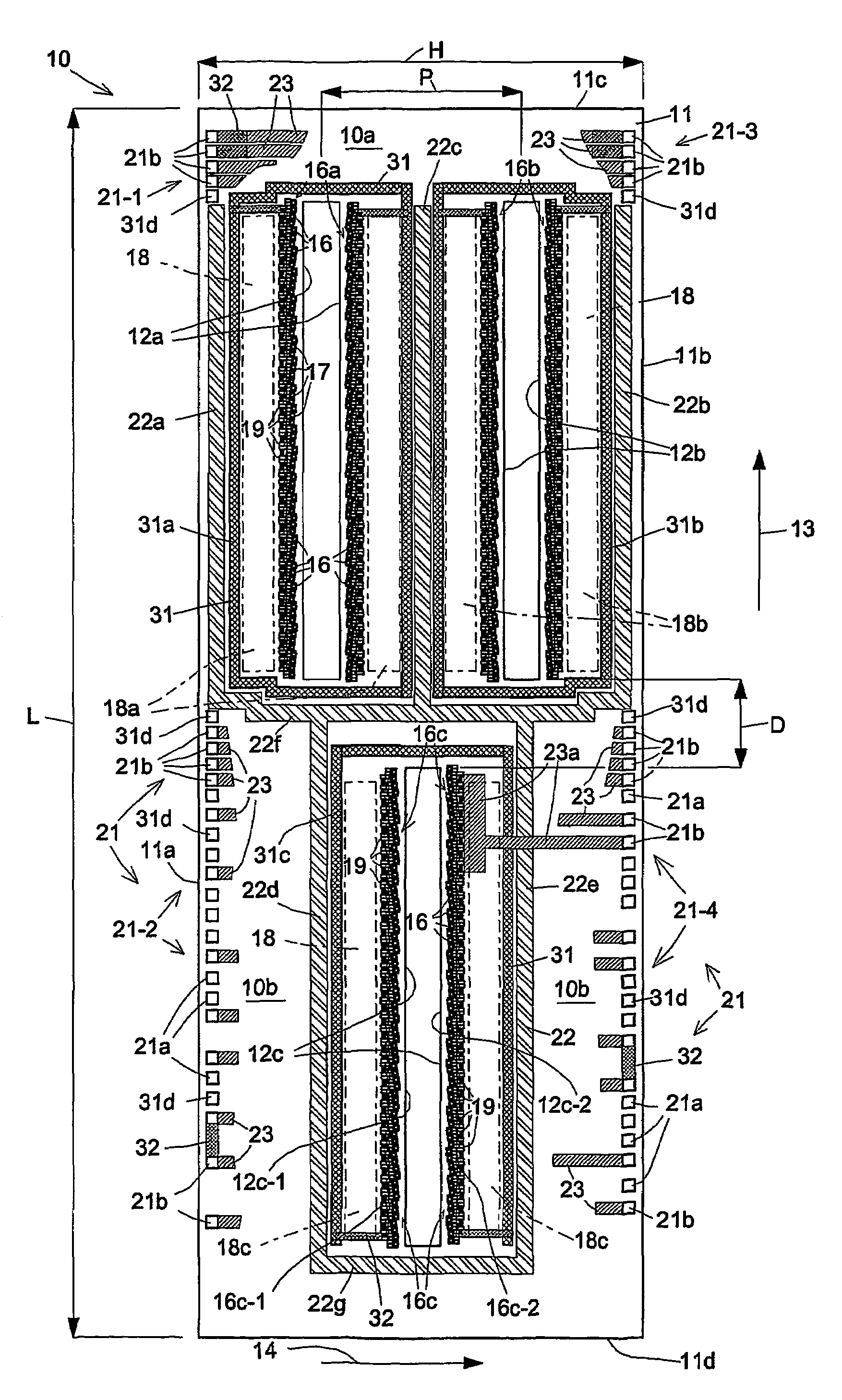
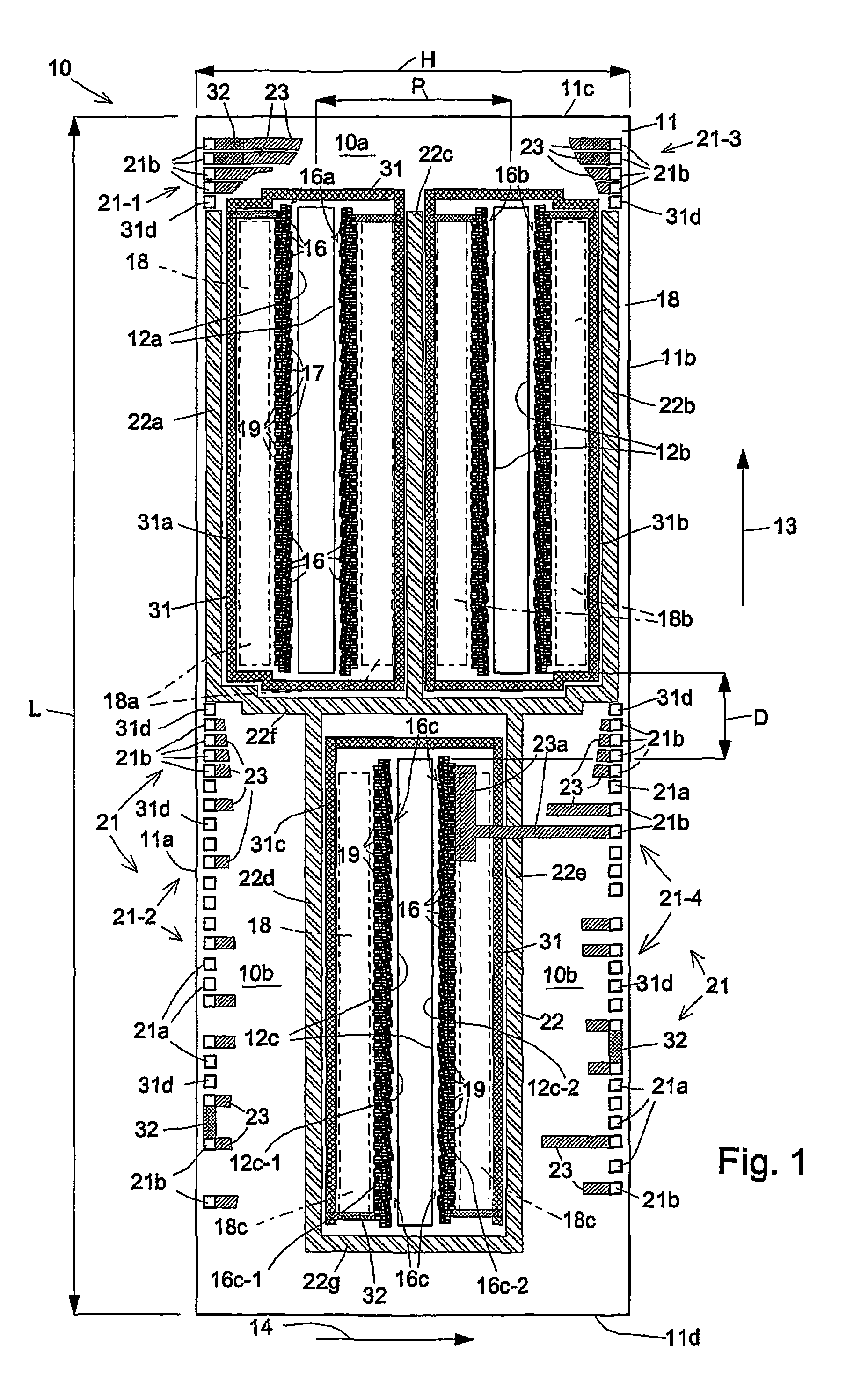
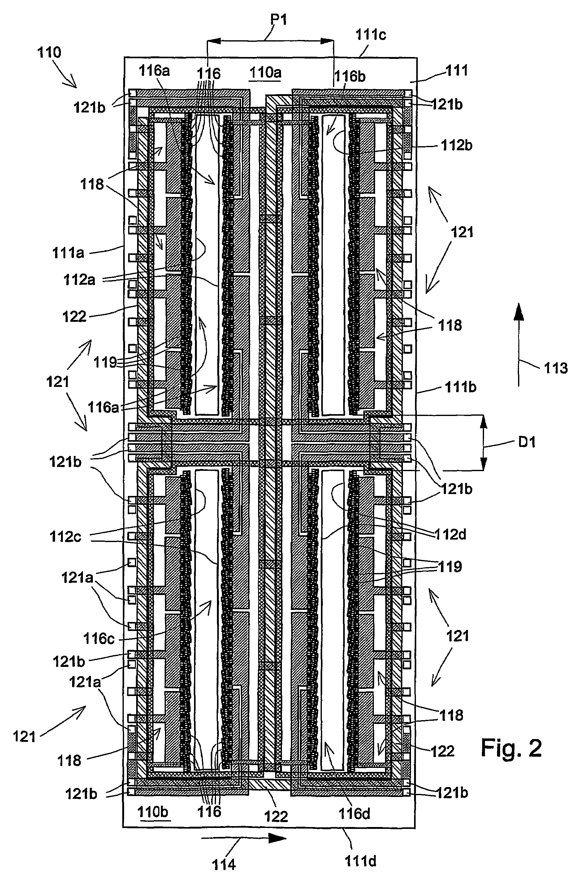
[0157]the substrate according to the invention is depicted in FIG. 2 and is generically indicated with the numeral 110.

[0158]For simplicity's sake, the parts corresponding to those already described in relation to the substrate 10 shall be designated with the same reference numerals plus 100.

[0159]The substrate 110 comprises a rectangular silicon plate 111 having two long opposite sides 111a e 111b which are oriented in a vertical direction 113, and two short sides 111c and 111d parallel to a horizontal direction 114, corresponding in turn to the motion of the substrate 110 during printing.

[0160]The substrate 110 differs from the substrate 10 in that, instead of three, it has four slots 112a, 112b, 112c and 112d, parallel to one another, extending in the lengthwise direction parallel to the vertical direction 113.

[0161]These four slots 112a, 112b, 112c and 112d are divided into an upper pair consisting of the slots 112a and 112b and are arranged in an upper semi-portion 110a of the ...

third embodiment

[0175]the substrate the subject of this invention is illustrated in FIG. 3 and is designated with the numeral 210.

[0176]For simplicity's sake, the parts corresponding to those relative to the first embodiment 10 of the substrate of this invention shall be designated with the same reference numerals plus 200.

[0177]The substrate 210 comprises a rectangular silicon plate 211 having two long opposite sides 211a and 211b which are oriented in a vertical direction 213, and two short sides 211c and 211d oriented in a horizontal direction 214, corresponding in turn to the motion of the substrate 210 during printing.

[0178]The substrate 210 also comprises four slots 212a, 212b, 212c and 212d, which extend parallel to one another lengthwise according to the vertical direction 213.

[0179]These four slots 212a, 212b, 212c and 212d are divided into an upper pair consisting of the slots 212a and 212b and arranged in an upper semi-portion 210a of the substrate 210, and into a lower pair consisting o...

fourth embodiment

[0191]A fourth embodiment, generically designated with the numeral 310, of the substrate the subject of this invention is represented schematically in FIG. 4.

[0192]According to the format already used for the preceding cases, the parts of this fourth embodiment of the substrate corresponding to those of the first embodiment 10 shall be designated with the same reference numerals plus 300.

[0193]The substrate 310 comprises a thin rectangular plate of silicon 311 defining one right side or edge 311a and a left side or edge 311b, and which also has one long slot 312a arranged along a left portion of the substrate 310, and three short slots, indicated respectively with 312b, 312c and 312d, arranged along a left portion of the substrate 310, wherein all four slots are made through the thickness of the plate 311 and are oriented in a vertical direction 313 parallel to the sides 311a and 311b.

[0194]In particular, the three short slots 312b, 312c and 312d are arranged in a line among one an...


PUM


Abstract

A substrate (10; 110; 210; 310) for an ink jet printhead comprising: at least three slots (12a, 12b, 12c) of elongated shape, oriented parallel to one another lengthwise in a vertical direction (13); three corresponding actuating banks (16a, 16b, 16c); a plurality of drive circuits (18); and a plurality of terminals (21, 21a, 21b), lesser in number than the ejection actuators (16), connected to the drive circuits (18) for receiving external signals, wherein at least two (12a, 12b) of the three slots are arranged side by side along the respective long edges in an upper portion (10a) of the substrate, and the third slot (12c) is arranged in a lower portion (10b) of the substrate, and wherein moreover the terminals (21) connected to the drive circuits are arranged in a line along the edges (11a, 11b) of the substrate (10) parallel to the slots and therefore to this given vertical direction (13). This substrate has a robust structure and is less likely to crack in the zone of the slots.

Description

[0001]This is a U.S. National Phase Application under 35 USC 371 and applicant herewith claims the benefit of priority of PCT / IT02 / 00163 filed on Mar. 18, 2002, which was published Under PCT Article 21(2) in English, and of Application No. TO2001A000266 filed in Italy on Mar. 21, 2001.TECHNICAL FIELD[0002]This invention relates to a substrate which is employed in the manufacture of ink jet printheads, particularly of the thermal type, and more specifically to a substrate comprising a plurality of ejection actuators for activating the ejection of ink droplets, a plurality of elongated slots or channels for conveying the ink from a tank to the ejection actuators, and a plurality of drive circuits associated with the ejection actuators for addressing them and commanding their activation.[0003]This invention also relates to an ink jet printhead that incorporates a substrate having the above-mentioned characteristics.BACKGROUND ART[0004]A substrate, like the one described summarily above...

Claims


Application Information

Patent Timeline
Patent Type & Authority Patents(United States)
IPC IPC(8): B41J2/05B41J2/21B41J2/14B41J2/15
CPCB41J2/15B41J2/14072
Inventor CONTA, RENATOMANINI, ENRICOMENEGATTI, ANGELO
Owner OLIVETTI I JET
Why Eureka
Try Eureka