Two panel optical engine for projection applications

a technology of optical engines and projection applications, applied in optics, instruments, projectors, etc., can solve the problems of affecting the development of cost-effective liquid crystal on silicon display devices for projection applications, unduly increasing the production cost of such systems, and achieving low cost and high-quality color display effects

Inactive Publication Date: 2006-03-07
JASPER DISPLAY
View PDF8 Cites 11 Cited by
  • Summary
  • Abstract
  • Description
  • Claims
  • Application Information

AI Technical Summary

Benefits of technology

[0010]It is therefore an object of the present invention to provide new and simplified means to process color path separation through polarization modifications and then recombination to achieve flexibly manageable color intensity adjustments dependent upon the background color of particular light source. The new and simplified color path separation and polarization modifications employ dichroic trim filters and optical retarder that are commercially available and of low cost while achieve high quality color display effect such that the aforementioned difficulties and limitations can be overcome.

Problems solved by technology

However, some of the configurations as developed earlier now become quite costly when the microdisplay systems are commercialized for high definition TVs and used as monitor for computers.
One particular system is the simplified two panels display configurations while cost savings are achieved with two instead of three color display panels, the optical components used for color path separation and polarization modifications as disclosed by the conventional configurations are specially made thus unduly increases the production cost of such systems.
It is well known that the complexity of on-axis optical engines has hindered the development of cost-effective liquid crystal on silicon display devices for projection applications.
The earliest attempts to solve this problem have required compromises.
The optical architecture therein is efficient and practical, but suffers in application because of the high cost and limited supply of the color selective retarder stacks.

Method used


Image

  • Two panel optical engine for projection applications
  • Two panel optical engine for projection applications
  • Two panel optical engine for projection applications

Examples


Embodiment Construction

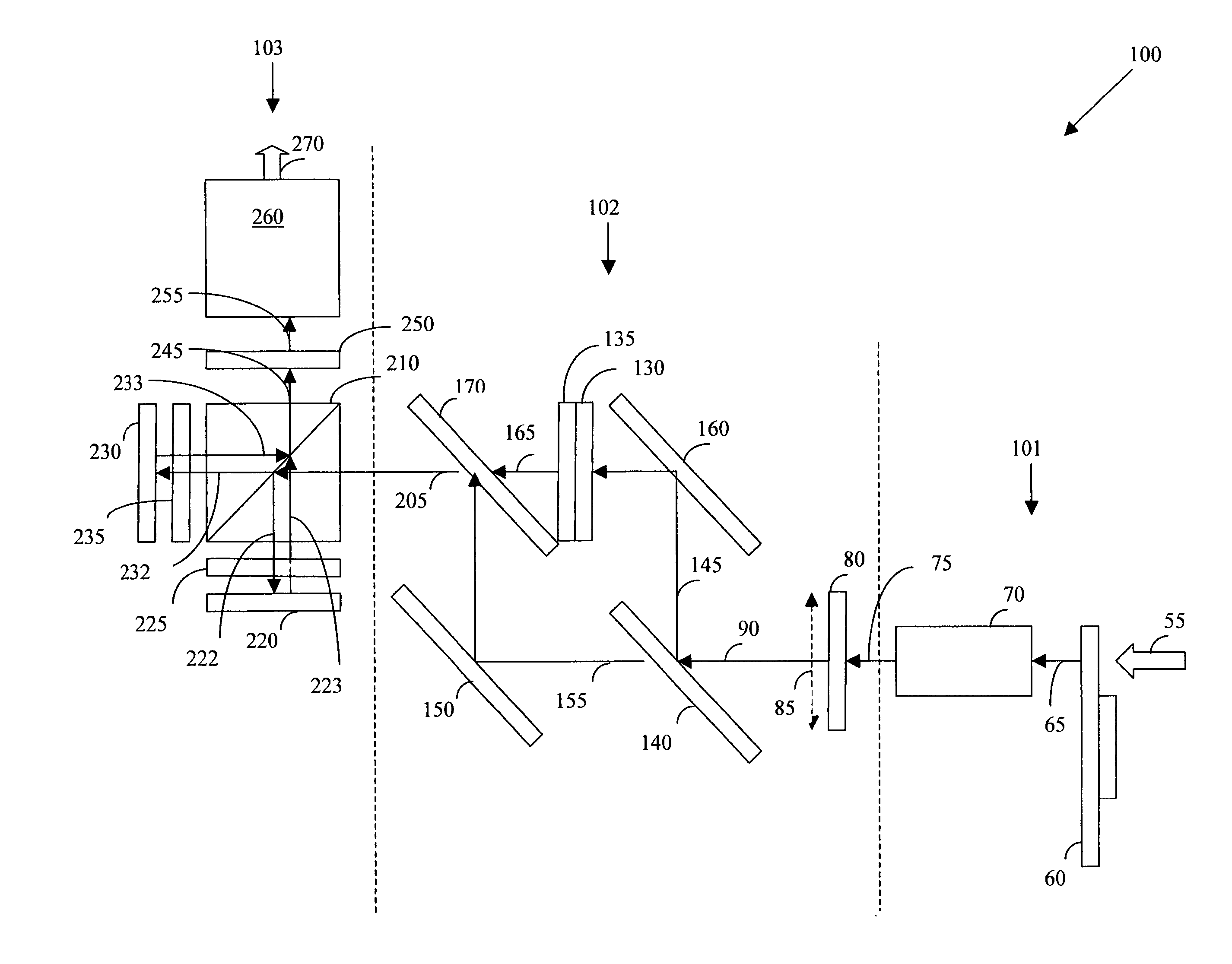
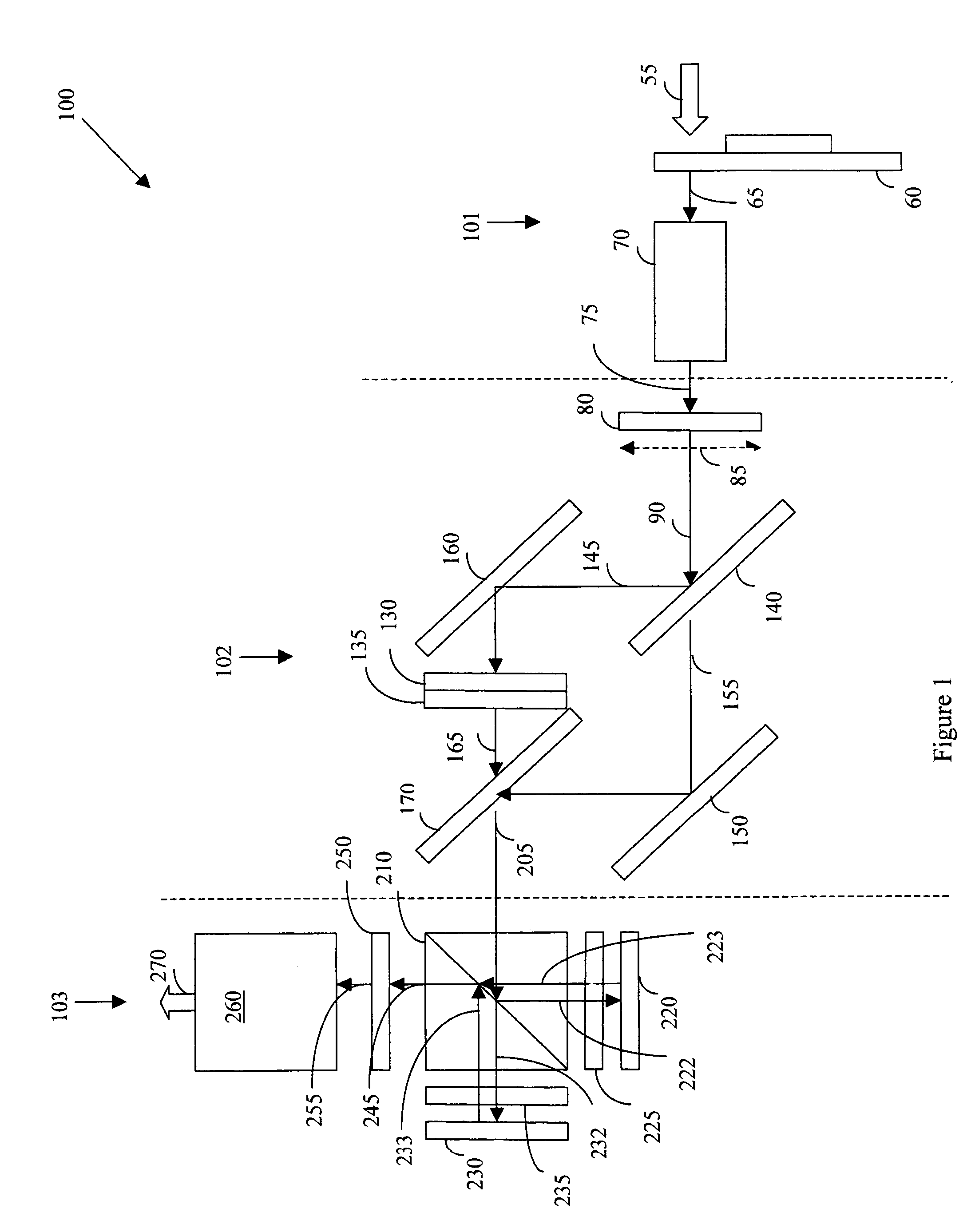
[0016]Referring to FIG. 2 for a two-panel engine 100 of this invention. The two panel optical engine 100 as shown in FIG. 2 can be divided into three major subsections. These three subsections are 1) an illumination subsection 101 for providing illumination for the optical engine; 2) a color generation, polarization and color separating subsection 102 that includes a means for separating different colors into orthogonal polarization states, and imaging and 3) a projection subsection 103 that includes means for generating composite color images.

[0017]In the illumination subsection 101, a high intensity discharge (HID) lamp or other suitable illumination generating system generates an illumination beam of light 55. A reflector, integrating sphere, or other suitable means is used to focus the light from the HID lamp. Since the specific details of the means for focusing the light beam is not part of the invention, for the sake of clarity, these details are not further provided. The illu...


PUM


Abstract

Optical engines using a reduced number of components offer advantages over more complex optical systems. Three panel optical engines have offered the advantage of relatively high throughput but at the cost of complexity and increased components on the bill of materials. Conventional two-panel engines have required the use of complex retarder structures to achieve the dual polarizations state for the three primary colors. The present invention achieves this goal while using simpler optical retarders.

Description

[0001]This Application is a Formal Application and claim a Priority Date of Nov. 5, 2002 benefited from a Provisional Patent Application 60 / 424,213 file by one common inventor of this Patent Application.BACKGROUND OF THE INVENTION[0002]1. Field of the Invention[0003]The present invention pertains to liquid crystal display (LCD) systems, and more particularly to improved two panel optical engines using simpler optical retarder for color display projection.[0004]2. Description of the Prior Art[0005]As earlier research projects in developing microdisplay systems using the liquid crystal display technologies were mostly for military and specialized applications with high performance requirements, the systems were generally configured without much concern for production costs. However, some of the configurations as developed earlier now become quite costly when the microdisplay systems are commercialized for high definition TVs and used as monitor for computers. One particular system is ...

Claims


Application Information

Patent Timeline
Patent Type & Authority Patents(United States)
IPC IPC(8): G03B21/14G02B5/22G03B21/00G02B27/14G02B27/28
CPCG02B27/1026G02B27/283G02B27/145
Inventor MCDONALD, DAVID CHARLES
Owner JASPER DISPLAY
Why Eureka
Try Eureka