Connector, a connector assembly and an assembling method

a technology of connectors and connector assemblies, applied in the direction of incorrect coupling prevention, coupling device connection, electrical apparatus, etc., can solve the problem of limiting the movement of sliders insufficiently, and achieve the effect of preventing the disengagement of interlocking

Inactive Publication Date: 2006-03-07
SUMITOMO WIRING SYST LTD
View PDF6 Cites 6 Cited by
  • Summary
  • Abstract
  • Description
  • Claims
  • Application Information

AI Technical Summary

Benefits of technology

[0009]Movement of the locking projection over the receiving portion is guided by the guiding surface as the slider is assembled into the first housing. Thus assembling efficiency is good. In the assembled state, the locking projection escapes into the escaping groove and engages the receiving portion to prevent the slider from coming out.
[0011]The locking projection preferably includes the restricting portion that bulges more outward than the guiding surface and that engages the peripheral edge of the escaping groove to restrict the displacement of the slider along the direction intersecting the moving direction of the slider. Thus, an area of engagement of the locking projection with the escaping groove is increased by as much as the restricting portion bulges out from the guiding surface. As a result, displacement of the slider is restricted sufficiently. Further, providing the guiding surface as before ensures a satisfactory assembling operation.
[0013]The slider preferably prevents disengagement of interlocking means that interlocks the two properly connected housings together.

Problems solved by technology

As a result, displacement of the slider is restricted sufficiently.

Method used


Image

  • Connector, a connector assembly and an assembling method
  • Connector, a connector assembly and an assembling method
  • Connector, a connector assembly and an assembling method

Examples


Embodiment Construction

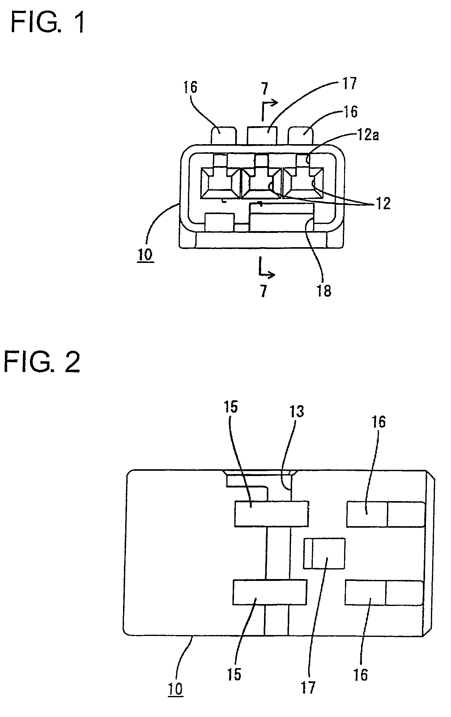
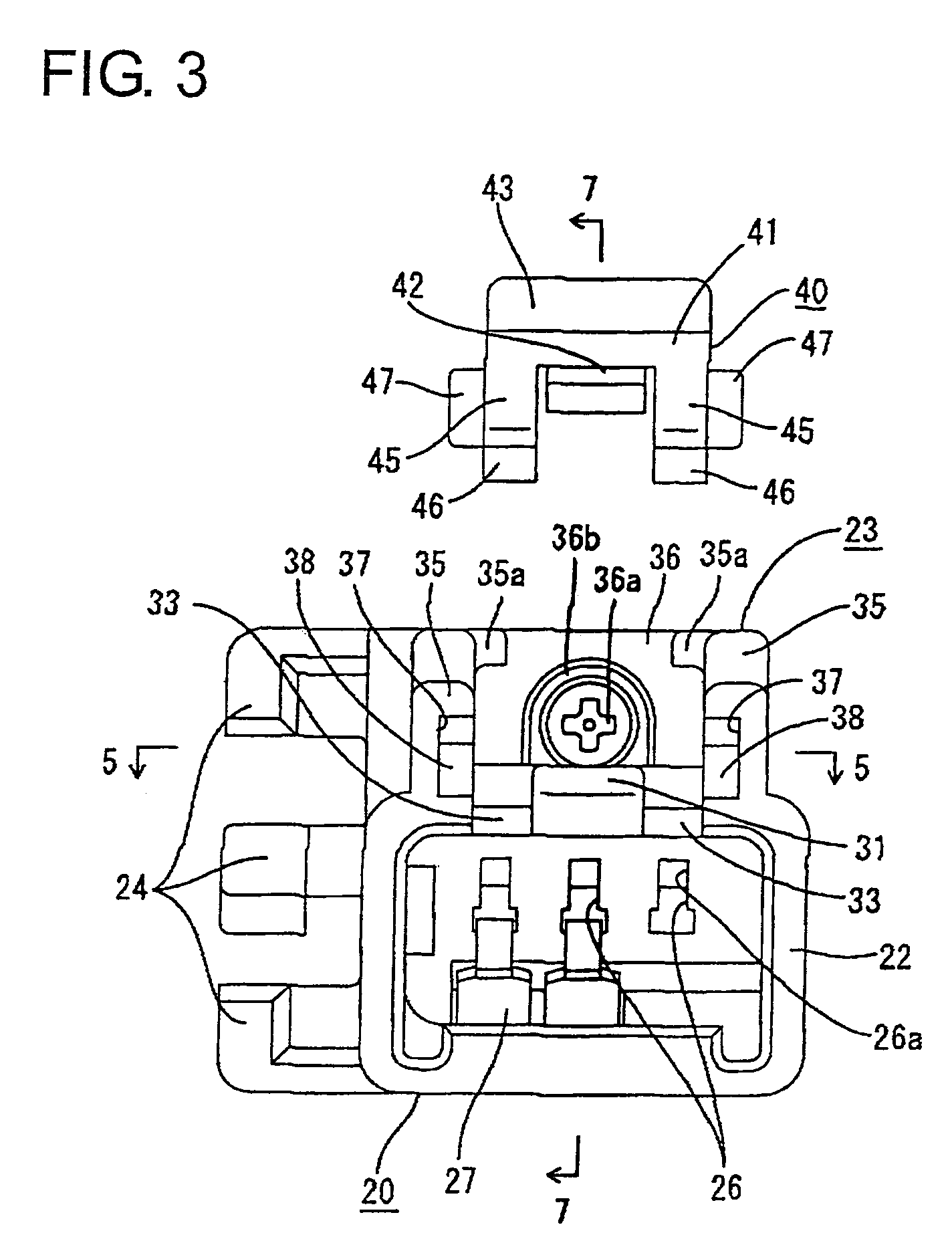
[0039]A connector according to the invention is described with reference to FIGS. 1 to 18. The connector includes a female housing 10 and a male housing 20 that are connectable to one another. In the following description, engaging sides of the two housings 10, 20 are referred to as front sides, and reference is made to all the figures except FIGS. 4, 5, 10 and 11 concerning vertical direction.

[0040]The female housing 10 is made e.g. of a synthetic resin and is substantially in the form of a block. Female terminal fittings 11 are insertable from behind into each of three cavities 12 that are arranged substantially side by side along a widthwise direction in the female housing 10. Each female terminal fitting 11 has a substantially box-shaped main portion 11a and a barrel 11b that are coupled one after the other. The main portion 11a is electrically connectable with a male terminal fitting 25, and the barrel 11b is configured to be crimped, bent or folded into connection with an end ...


PUM


Abstract

A slider (40) is movable forward and back in a male housing (20) and is pushed back as a female housing (10) is connected with the male housing (20). A compression coil spring (S) accumulates a biasing force as the slider (40) is moved back. The male housing (20) has escaping grooves (37) for receiving locking projections (47) of the slider (40) and receiving portions (38) engageable with the locking projections (47) to prevent the slider (40) from coming out. Each locking projection (47) has a guiding surface (48a) for guiding the locking projection (47) over the receiving portion (38) when the slider (40) is assembled, and a restriction (49) for engaging an upper edge (37a) of the escaping groove (37) and restricting upward displacement of the slider (40). The restricting portions (49) bulge out more than the guiding surface (48a).

Description

BACKGROUND OF THE INVENTION[0001]1. Field of the Invention[0002]The invention relates to a connector with a partial connection preventing function.[0003]2. Description of the Related Art[0004]U.S. Pat. No. 6,685,400 and FIGS. 19(A) and 19(B) herein disclose a connector with a partial connection preventing function. Similar connectors are shown in U.S. Pat. No. 6,520,786, U.S. Pat. No. 6,595,797 and U.S. Pat. No. 6,679,720. With reference to FIGS. 19(A) and (B), the connector has a male housing 1 with a receptacle 1a and a female housing 2 that can fit in the receptacle 1a. A slider 3 is assembled in sliding contact with the upper surface of the female housing 2 and is slidable forward and back along the connecting direction. A compression coil spring 4 is squeezed between the slider 3 and the female housing 2. The male housing 1 pushes the slider 3 back as the housings 1, 2 are being connected. Thus, the spring 4 is compressed resiliently and accumulates a biasing force to separate ...

Claims


Application Information

Patent Timeline
Patent Type & Authority Patents(United States)
IPC IPC(8): H01R3/00H01R13/627H01R13/64H01R13/629H01R13/635
CPCH01R13/635H01R13/6272H01R13/629
Inventor NAKAMURA, HIDETO
Owner SUMITOMO WIRING SYST LTD
Why Eureka
Try Eureka