Diaphragm pump and pump for double-breast pumping

a diaphragm pump and pump technology, applied in the field of motorized pumps, can solve the problems of not being able to double-pump off the same pump, requiring manual effort to operate, and the smaller battery-powered pumps which are part of the breast shield assembly itself have not been adapted to, or historically capable of, double-pumping off the same pump. , to achieve the effect of convenient portability and low cos

Inactive Publication Date: 2006-03-07
MEDELA HLDG AG
View PDF6 Cites 31 Cited by
  • Summary
  • Abstract
  • Description
  • Claims
  • Application Information

AI Technical Summary

Benefits of technology

[0007]The motor drive mechanism of the pump has a durable drive train, and the main vacuum-generating pump components—flexible diaphragm and rigid cap—are each preferably detachably mounted together within a frame. Assembly, and disassembly—as for repair or cleaning—are therefore efficiently and easily accomplished. A pressure regulator valve mechanism on the rigid cap further provides simple manual control for varying negative pressure developed by the pump.
[0015]In yet another embodiment, the vacuum regulator device takes the form of a ring element which is rotatably mounted on each of a pair of caps in a pump adapted for double breast pumping. The rotatable element is easily manipulated. This also enables independent control of the vacuum being generated in each breast shield assembly, for maximum convenience of the mother. The previously noted vacuum regulator devices above can likewise be used on each of the pump caps for the same advantageous independent control. Also, a continuously variable vacuum regulator device has been developed and can be used.
[0018]A common drive mechanism serves to operate both of the pressure chambers of this double-diaphragm pump. In the foregoing embodiment, the drive mechanism uses an offset push-pull arrangement to create alternating negative pressure in the respective chambers. This results in alternating suction on the breasts. The double-diaphragm pumping mechanism of this embodiment (which is mounted to a breast shield assembly) is compact and light enough to be readily supported on a single hand-held breast shield assembly, such that it can be held in place by the mother on one breast with one hand, while the other breast shield assembly, which is being run off of the same pump, is held in place with the other hand.

Problems solved by technology

For some mothers, breastpumps are required, particularly when the child has suckling difficulties, or if the mother has problems with excessive or deficient milk production, or cannot empty completely.
They also obviously require some manual effort to operate.
While eliminating the need for manually reciprocating the pumping mechanism, those pumps made for operating two breast shield assemblies at once—double-pumping—have typically been quite large, and often quite heavy.
Smaller battery-powered pumps which are part of the breast shield assembly itself have not historically been adapted to, or capable of, double-pumping off the same pump.

Method used


Image

  • Diaphragm pump and pump for double-breast pumping
  • Diaphragm pump and pump for double-breast pumping
  • Diaphragm pump and pump for double-breast pumping

Examples


case 14

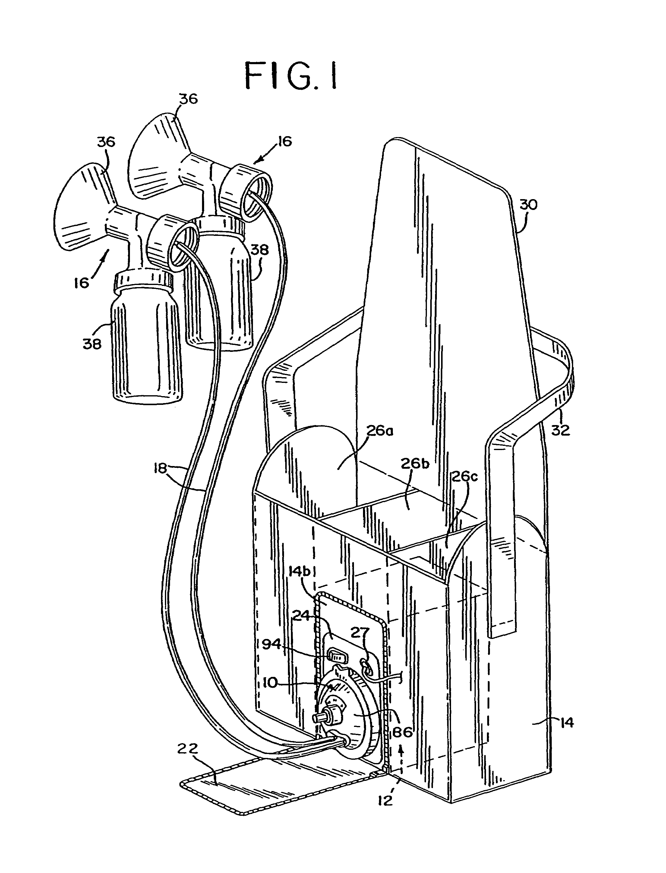
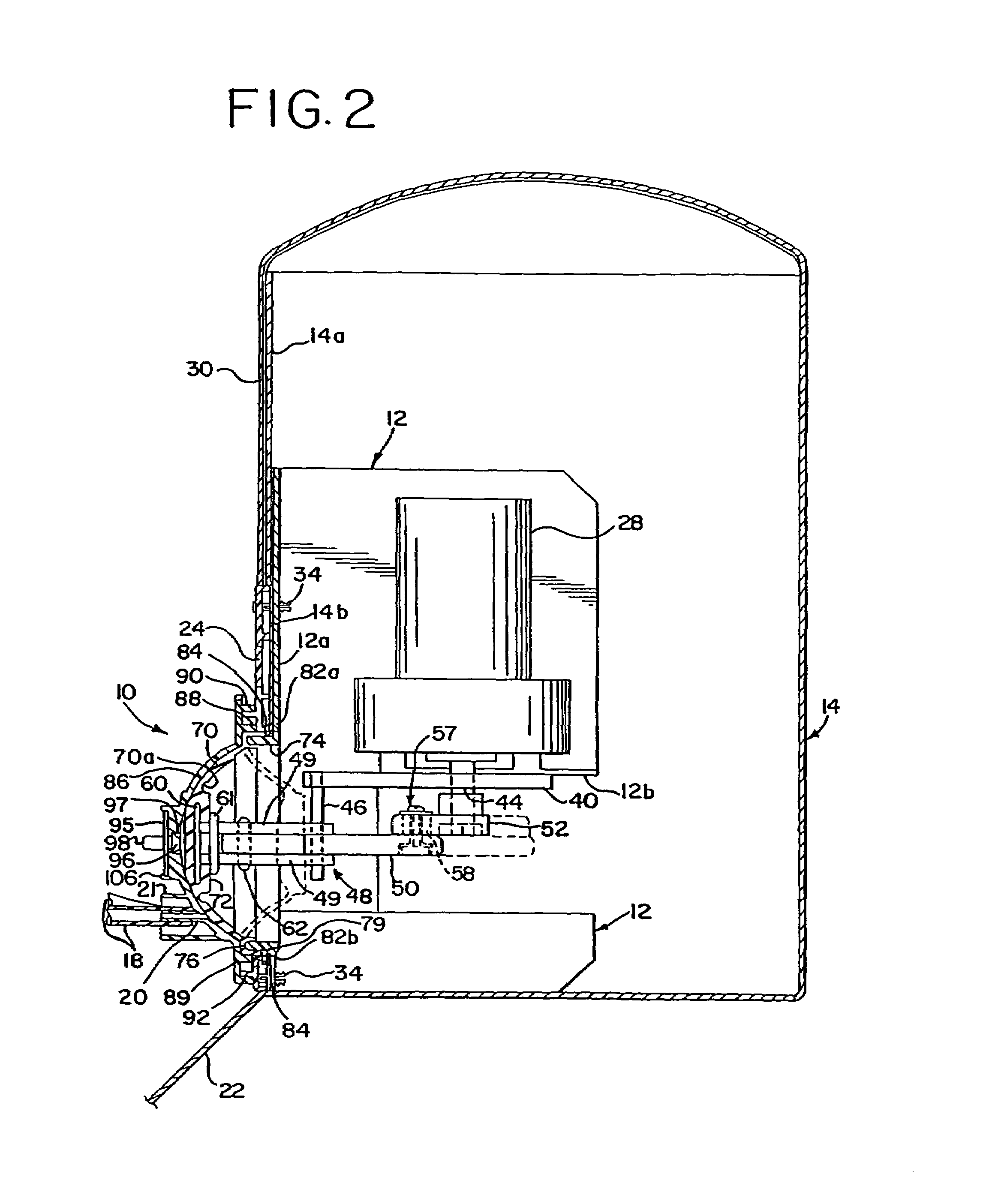
[0050]Case 14 has a number of interior compartments 26a, 26b, 26c, which constitute storage areas, such as for the breast shield assemblies 16, tubing 18, diapers, etc. Case 14 also could include a power source in the form of a battery (not shown) to which a commonly obtainable 12V DC gear motor 28 (FIG. 2) is electrically connected. An alternative power source could be an A.C. source (e.g., common 120 VAC service) through a DC converter, as at jack 27 (FIG. 1). The motor, power source and their various electrical connections are all conventional, and well known to those skilled in the art.

[0051]Case 14 has a flap-type closure 30, with a shoulder strap 32. Pump support frame 12 is fixed within a fabric compartment formed within the case 14. This may be by attachment of the front plate 24 to surrounding fabric 14b in a conventional manner, such as by riveting, stitching, adhering or some other common attachment. Here, front plate 24 frames the fabric 14b and captures it between the b...

embodiment 150

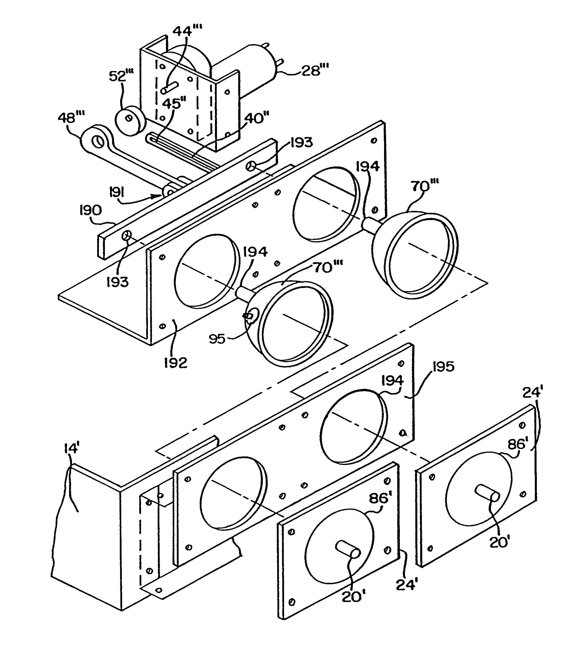
[0090]In this table-top embodiment 150, the caps 122′ are each provided with a vacuum regulation device. This takes the form of a flexible ring 160 which is mounted in a channel 161 (FIG. 16) formed in a collar portion 164 that extends outwardly from the cap 122′. Flexible ring 160 overlies a vent hole 165 which communicates with the space between the interior of the cap 122′ and the diaphragm 70″. The flexible ring 160 forms an air seal with the channel 161, except for a portion 166 comprising a small channel 166 in the ring 160. This small channel 166 is rotatable to positions where it will connect one, both or none of apertures 167a, 167b formed in the radially extending outboard lip 164a of the collar portion 164. This respectively will correspond to a previously determined medium (one aperture), minimum (both) or maximum (neither) vacuum pressure. This pressure regulation is advantageously independently provided for each breast shield in this manner.

[0091]Motor 28″ is actuated ...


PUM


Abstract

A motorized pump is disclosed that includes a flexible diaphragm fitting within a rigid member, a motor drive mechanism for drawing a puller member attached to the diaphragm away from the rigid member to create a space between the diaphragm and the rigid member and form a negative pressure region within that space, and an outlet communicating with the negative pressure region. In one embodiment, the pump provides a negative pressure in a single chamber which can be used to operate one or two breast shield assembles. In another embodiment, the pump is particularly adapted for double-pumping and provides two chambers which generate vacuum.

Description

RELATED PATENT APPLICATIONS[0001]This patent application is a divisional application from U.S. application Ser. No. 09 / 055,101 (filed Apr. 3, 1998, to be issued as U.S. Pat. No. 6,257,847 on Jul. 10, 2001) which is a continuation-in-part of U.S. Ser. No. 08 / 510,714 (filed Aug. 3, 1995), now U.S. Pat. No. 5,776,098 (issued Jul. 7, 1998).BACKGROUND OF THE INVENTION[0002]The invention relates to motorized pumps, and more particularly, to breastpumps.[0003]Breastpumps are convenient for nursing mothers, because, among other things, they allow the nursing mother to draw off breast milk to feed to the child at a later time when the mother may not be present. For some mothers, breastpumps are required, particularly when the child has suckling difficulties, or if the mother has problems with excessive or deficient milk production, or cannot empty completely. Some mothers also require breastpumps in the event of soreness or injury of the mammilla, or sunken mammilla.[0004]Manually-driven bre...

Claims


Application Information

Patent Timeline
Patent Type & Authority Patents(United States)
IPC IPC(8): A61M1/06A01J5/04A61M1/00F04B9/04F04B43/00F04B45/04F04B45/047F04B49/22
CPCA61M1/06F04B9/045A61M1/0072F04B45/043F04B45/047F04B49/225F04B43/0063A61M1/0037A61M1/75A61M1/82
Inventor SILVER, BRIAN H.ANNIS, LARRY D.
Owner MEDELA HLDG AG
Why Eureka
Try Eureka