Dual durometer elastomer artificial disc

a technology of artificial discs and durometers, applied in the field of dual durometer elastomer artificial discs, can solve problems such as separation from the rest of the dis

Inactive Publication Date: 2006-03-07
DEPUY ACROMED INC
View PDF27 Cites 62 Cited by
  • Summary
  • Abstract
  • Description
  • Claims
  • Application Information

AI Technical Summary

Benefits of technology

[0017]This invention is advantageous because the outer shell contacts the core along its sidewall surfaces as well, thereby providing more contact between these components, and reducing the chances of delamination therebetween.

Problems solved by technology

However, since it is known that the shear forces acting upon an intervertebral disc are quite significant, the endplates components of Lee and Parsons may be subject to such high shear forces that they may separate from the remainder of the disc.

Method used


Image

  • Dual durometer elastomer artificial disc
  • Dual durometer elastomer artificial disc
  • Dual durometer elastomer artificial disc

Examples


Embodiment Construction

[0035]For the sake of clarity, “durometer” is the term of art used in the field for the hardness of an elastomeric material.

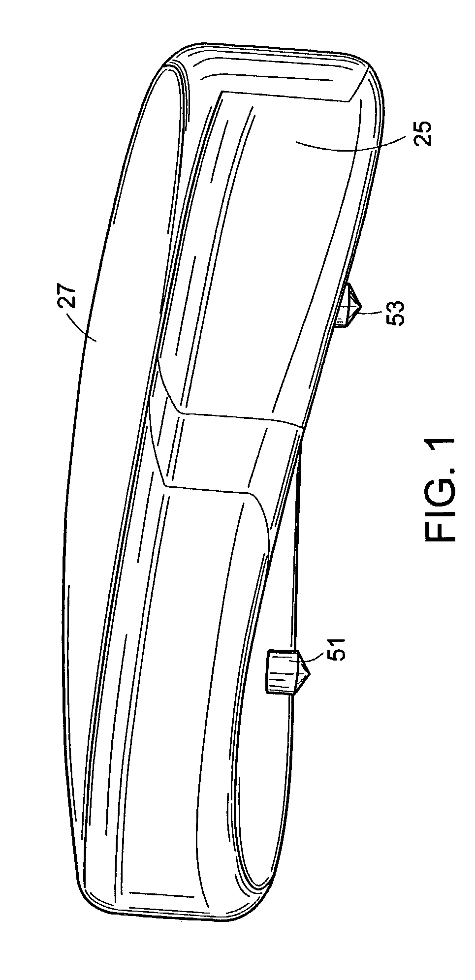
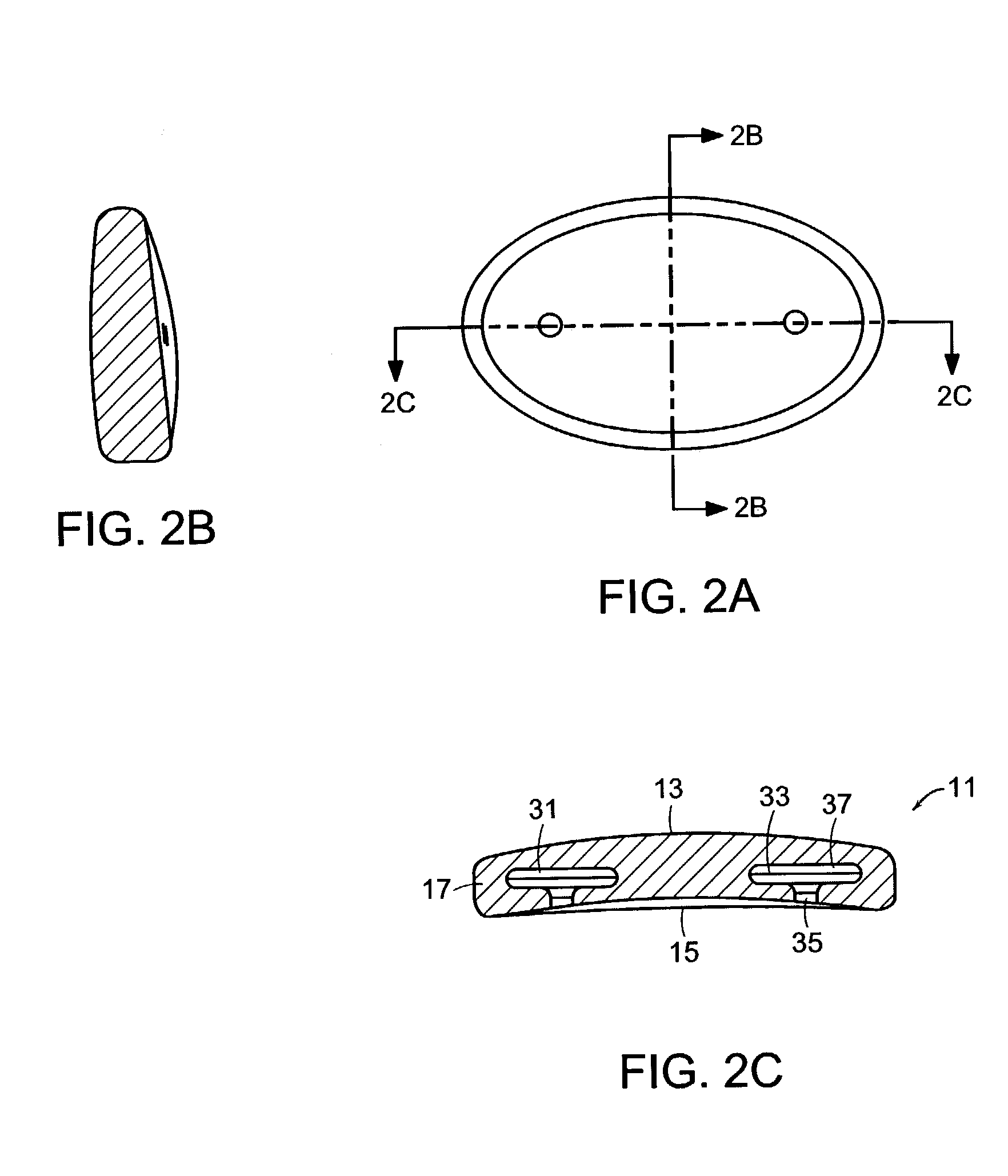
[0036]Now referring to FIGS. 1, 2a–c and 3a–c, there is provided an intervertebral disc 1 for insertion between opposed endplates of adjacent vertebral bodies, the disc comprising:

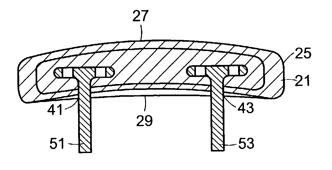
a) a central core material 11 having:

[0037]an upper surface 13, a lower surface 15 and a peripheral sidewall 17 therebetween, and[0038]first 31 and second 33 recesses extending into the core from the lower surface 15, each recess forming a necked portion 35 and a cavity 37,

b) a non-resorbable outer shell 21 having:[0039]an inner surface 23 surrounding the central core and contacting the upper surface, the lower surface and the sidewall of the core, and[0040]an outer surface 25 having an i) upper surface 27 adapted to contact a natural upper vertebral endplate and ii) a lower surface 29 adapted to contact a natural lower vertebral endplate, and[0041]first 41 and second 43 channels exte...


PUM


Abstract

An intervertebral motion disc comprising core material surrounded by a non-resorbable outer shell having a sidewall surrounding the core, wherein the sidewall of the outer shell has a hardness of more than 80 Shore A.

Description

BACKGROUND OF THE INVENTION[0001]In a normal spine, a healthy intervertebral disc can compress about 1 mm when subjected to an axial load of 750 pounds force (3.4 kN). This ability to compress in response to axial loads provides the spine with an effective shock absorber against high loads.[0002]The leading cause of lower back pain arises from rupture or degeneration of lumbar intervertebral discs. Pain in the lower extremities is caused by the compression of spinal nerve roots by a bulging disc, while lower back pain is caused by collapse of the disc and by the adverse effects of articulation weight through a damaged, unstable vertebral joint. One proposed method of managing these problems is to remove the problematic disc and replace it with a prosthetic disc that allows for the natural motion between the adjacent vertebrae (“a motion disc”).[0003]Many prosthetic motion discs seek to mimic the flexion, extension and lateral bending of the natural disc by providing an articulating ...

Claims


Application Information

Patent Timeline
Patent Type & Authority Patents(United States)
IPC IPC(8): A61F2/44A61F2/00A61F2/30
CPCA61F2/442A61F2/3094A61F2002/30016A61F2002/30069A61F2002/3008A61F2002/30133A61F2250/0098A61F2002/30563A61F2002/30795A61F2002/444A61F2230/0015A61F2230/0071A61F2250/0019A61F2002/30242
Inventor HAWKINS, JOHN R.
Owner DEPUY ACROMED INC
Why Eureka
Try Eureka