Low noise power transformer

a transformer and low noise technology, applied in the direction of transformer/inductance details, inductance, fixed inductance, etc., can solve the problem that the transformer can easily corrupt or even obscure the electrical parameter to be measured

Active Publication Date: 2006-03-07
KEITHLEY INSTRUMENTS INC
View PDF9 Cites 83 Cited by
  • Summary
  • Abstract
  • Description
  • Claims
  • Application Information

AI Technical Summary

Problems solved by technology

An unwanted common mode current from the transformer can easily corrupt or even obscure the electrical parameter to be measured.

Method used


Image

  • Low noise power transformer
  • Low noise power transformer
  • Low noise power transformer

Examples


Embodiment Construction

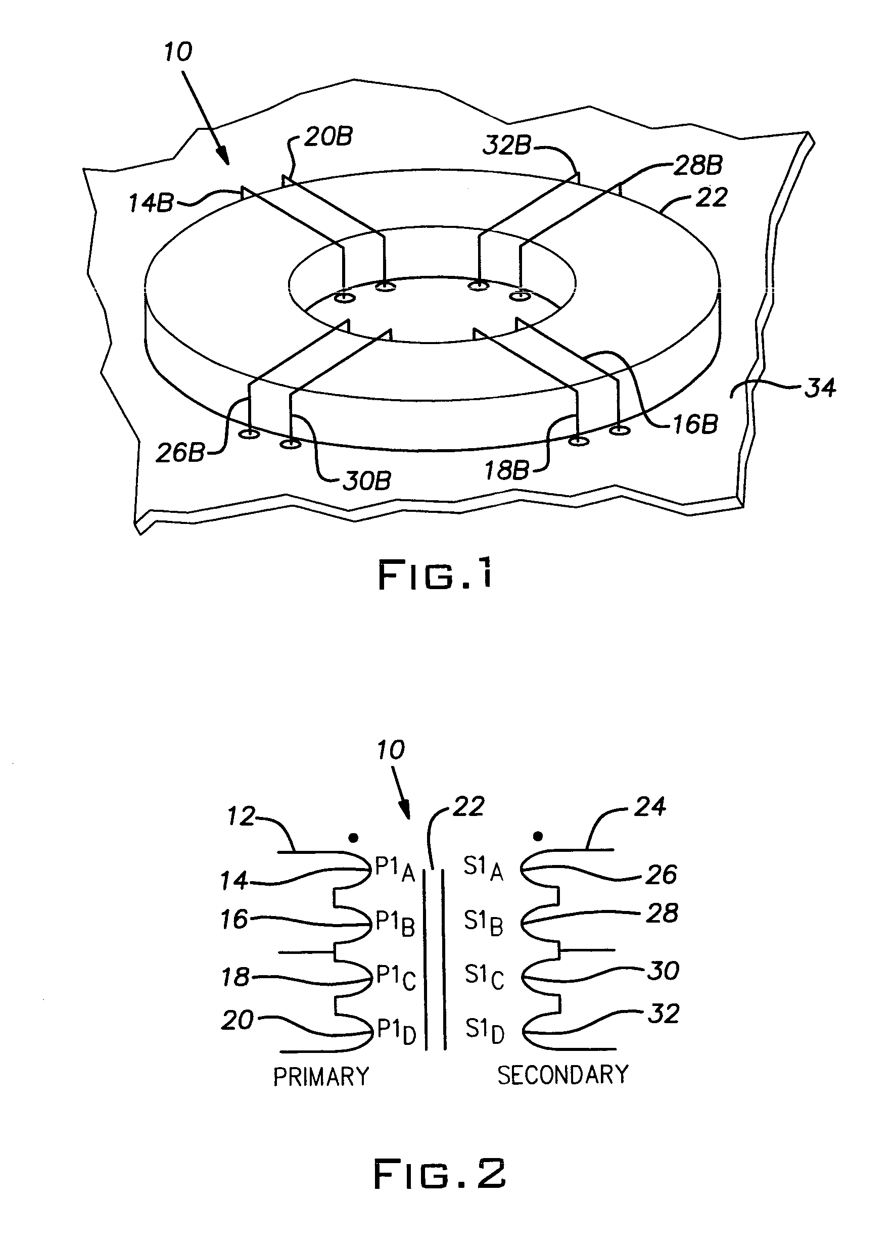
[0017]Referring to FIG. 2, a transformer 10 is shown schematically with a center-tapped primary winding 12 formed from the turns 14, 16, 18, 20. A magnetic core 22 couples the winding 12 to the center-tapped secondary winding 24 formed from the turns 26, 28, 30, 32.

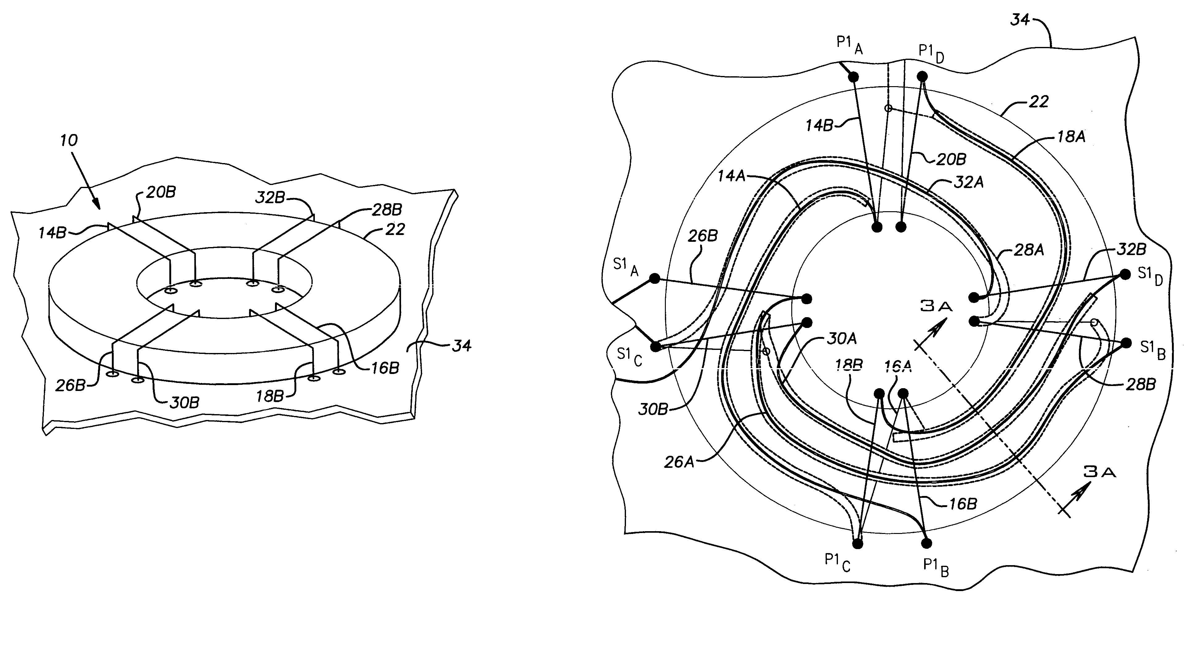
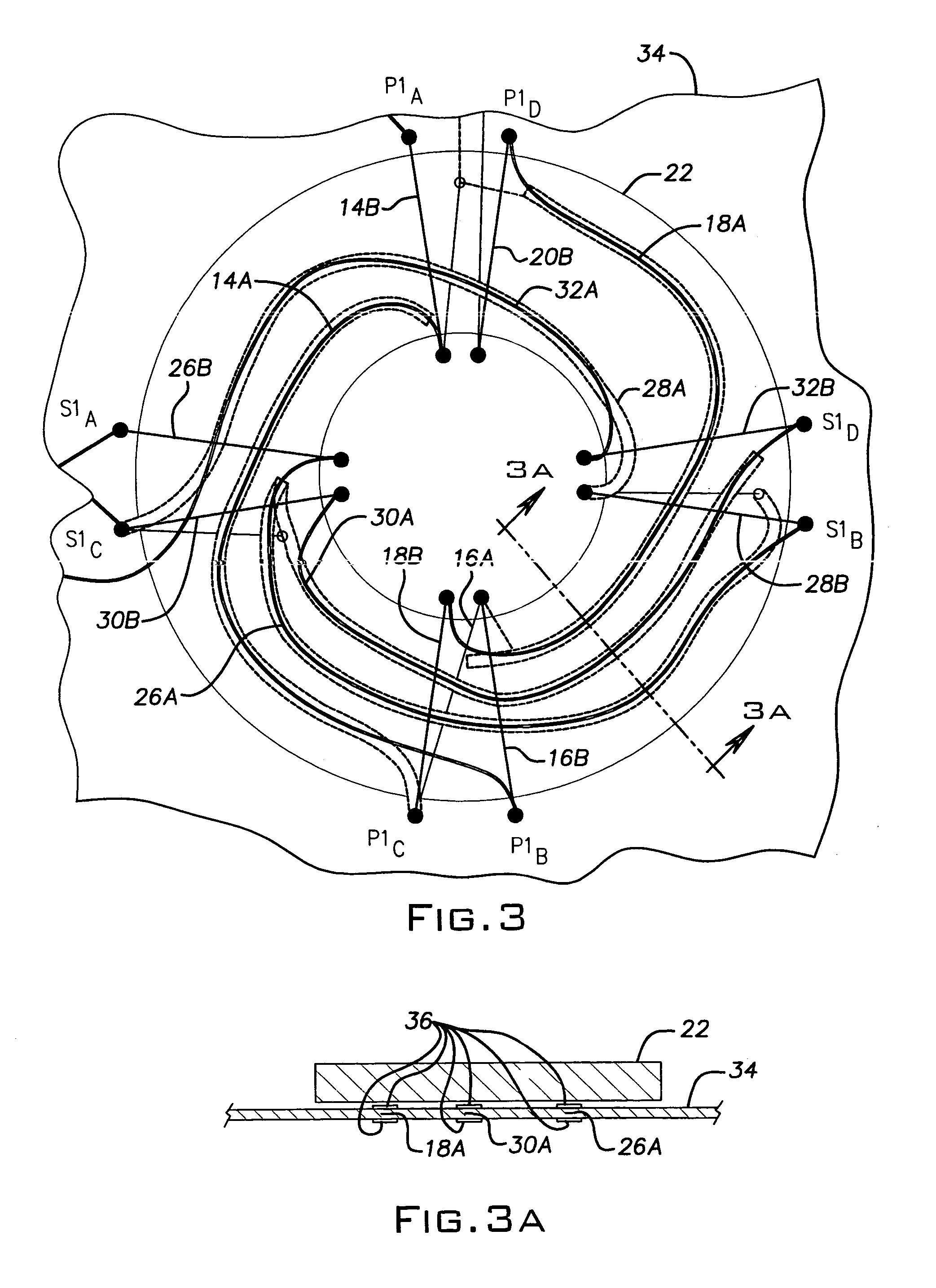
[0018]Referring to FIGS. 1 and 3, the transformer 10 may be advantageously implemented with an annular magnetic core 22; a printed circuit board 34 containing traces 14A, 16A, 18A, 20A forming first portions of the winding 12, and traces 26A, 28A, 30A, 32A forming first portions of the winding 24; and staple-like conductors staples 14B, 16B, 18B, 20B forming second portions of the winding 12 and staples 26B, 28B, 30B, 32B forming second portions of the winding 24.

[0019]The core 22′ is enlaced by the staples 14A, 16B, 18B, 20B, 26B, 28B, 30B, 32B when they are electrically and mechanically connected to the board 34, for example, by soldering.

[0020]The board 34 may advantageously be of a multilayer type with for example, (s...


PUM

PropertyMeasurementUnit
electricallyaaaaaaaaaa
electrical parameteraaaaaaaaaa
magneticaaaaaaaaaa

Abstract

A printed circuit board transformer has primary and secondary windings. The transformer includes a printed circuit board having a plurality of traces forming a plurality of first portions of the primary and secondary windings, an annular magnetic core adjacent to the printed circuit board, and a plurality of second portions of the primary and secondary windings. The second portions are formed from conductors enlacing the core.

Description

BACKGROUND OF THE INVENTION[0001]The present invention relates to low noise transformers and, in particular, to transformers with low common mode noise.[0002]In sensitive measurement equipment, the power transformer is often used to provide isolation from the measurement circuit. An unwanted common mode current from the transformer can easily corrupt or even obscure the electrical parameter to be measured.[0003]Bulky transformers with expensive internal shields are commonly used to limit the common mode current to acceptable noise levels.[0004]An inexpensive, compact, transformer with the desired characteristics would permit a less expensive and more compact measurement instrument to be produced.SUMMARY OF THE INVENTION[0005]A printed circuit board transformer has primary and secondary windings. The transformer includes a printed circuit board having a plurality of traces forming a plurality of first portions of the primary and secondary windings, an annular magnetic core adjacent t...

Claims


Application Information

Patent Timeline
Patent Type & Authority Patents(United States)
IPC IPC(8): H01F27/28
CPCH01F30/16H01F27/2804H01F17/0033H01F17/062H01F2027/2814
Inventor GOEKE, WAYNESYPEN, ART
Owner KEITHLEY INSTRUMENTS INC
Why Eureka
Try Eureka