Timing generator and test apparatus

a technology of time generator and test apparatus, which is applied in the direction of digital signal error detection/correction, cathode-ray oscilloscope, instruments, etc., can solve the problems of difficult to test the accuracy of electronic devices and difficult to judge accurately

Inactive Publication Date: 2006-03-07
ADVANTEST CORP
View PDF9 Cites 23 Cited by
  • Summary
  • Abstract
  • Description
  • Claims
  • Application Information

AI Technical Summary

Benefits of technology

[0007]Accordingly, it is an object of the present invention to provide a timing generator and a test apparatus, which is capable of overcoming the above drawbacks accompanying the conventional art. The above and other objects can be achieved by combinations described in the independent claims. The dependent claims define further advantageous and exemplary combinations of the present invention.

Problems solved by technology

However, since the conventional test apparatus judges the quality of the electronic device by one measurement, it is difficult to judge accurately due to the jitter component in both the output signal and the data strobe.
However, since it is impractical that a memory for storing such enormous amounts of phase data is provided in the test apparatus and besides storing all of the phase data of the sampling timing signals to be produced is nearly impossible, so it is difficult to test the electronic device highly accurately.

Method used


Image

  • Timing generator and test apparatus
  • Timing generator and test apparatus
  • Timing generator and test apparatus

Examples


Embodiment Construction

[0024]The invention will now be described based on the preferred embodiments, which do not intend to limit the scope of the present invention, but exemplify the invention. All of the features and the combinations thereof described in the embodiment are not necessarily essential to the invention.

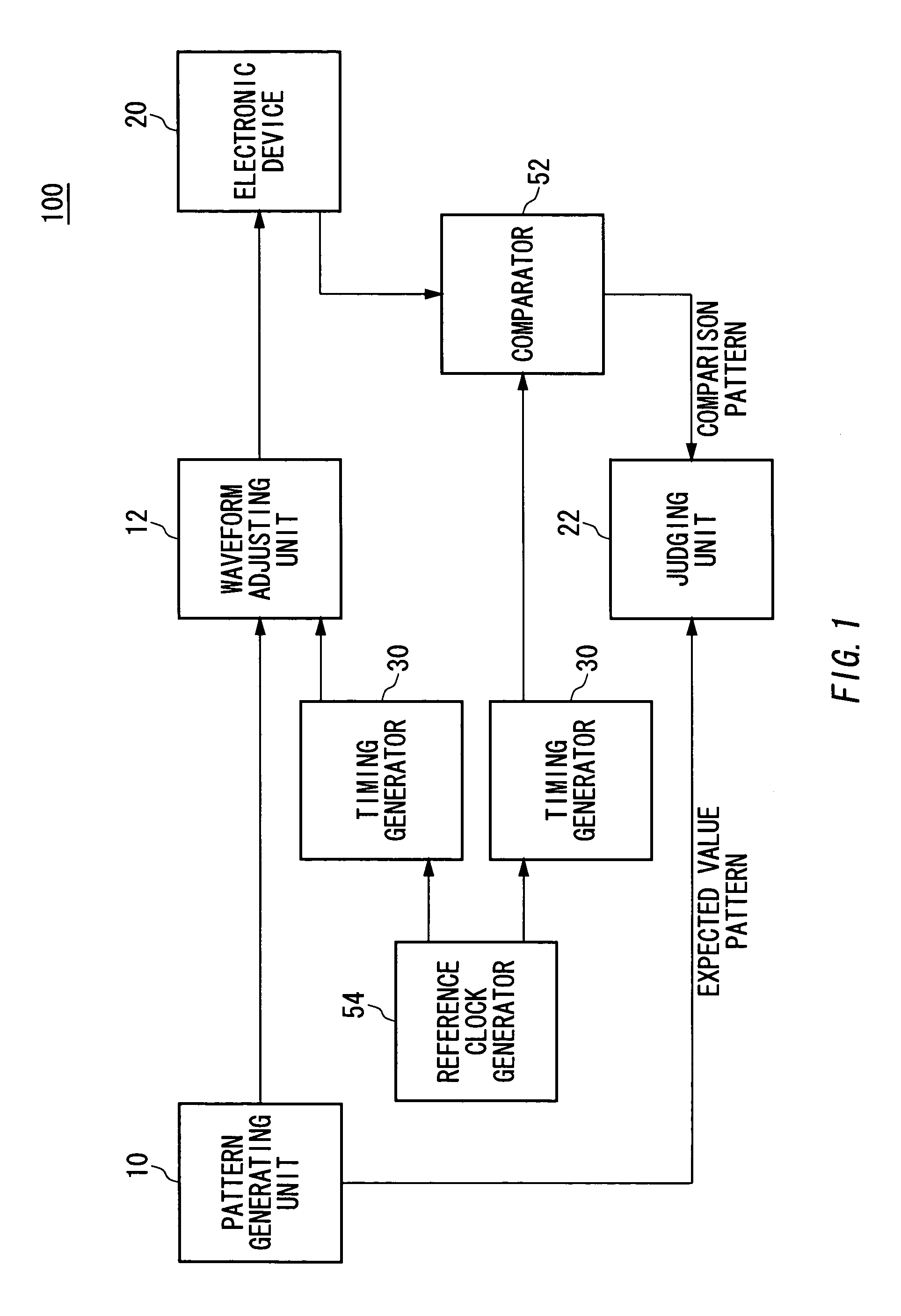
[0025]FIG. 1 shows an example of the configuration of a test apparatus 100 according to the present invention. The test apparatus 100 includes a reference clock generating unit 54 for generating a reference clock, a pattern generating unit 10 for generating a test pattern synchronously with the reference clock, a timing generator 30 for generating a timing signal based on the reference clock, a waveform formatting unit 12 for generating an formatted pattern which results from formatting the test pattern and inputting the formatted pattern to the electronic device 20 at the timing based on the timing signal generated by the timing generator 30, a comparator 52 for obtaining a comparison patter...


PUM

PropertyMeasurementUnit
timeaaaaaaaaaa
timeaaaaaaaaaa
phaseaaaaaaaaaa

Abstract

A timing generator includes a reference clock generating unit for outputting a reference clock at a predetermined time interval, a first variable delay circuit unit for receiving the reference clock and outputting a first delay signal which results from delaying the reference clock, a second variable delay circuit unit for receiving the reference clock and outputting a second delay signal which results from delaying the reference clock, a delay control unit for controlling delay amounts of the first and second variable delay circuit units, and a timing generating unit for generating the timing signal based on the first and second delay signals, wherein the first and second delay control units increase or decrease the delay amounts of the first and second variable delay circuit units to be increased or decreased whenever the reference clock generating unit generates the reference clock.

Description

[0001]The present application is a continuation application of PCT / JP02 / 11610 filed on Nov. 7, 2002, which claims priority from a Japanese patent application No. 2001-342955 filed on Nov. 8, 2001, the entire contents of which are incorporated herein by reference for all purposes.BACKGROUND OF THE INVENTION[0002]1. Field of the Invention[0003]The present invention relates to a timing generator for generating a timing signal and a test apparatus thereof.[0004]2. Related Art[0005]Recently, the trend towards a high speed electronic device such as a semiconductor device is considerable. For example, if there is jitter in the internal clock of a high speed memory device such as DDR-SDRAM, the jitter component is inevitably included in both the output data of the device and the data strobe which is a clock based on the internal clock and used for the transfer of the output data.[0006]However, since the conventional test apparatus judges the quality of the electronic device by one measureme...

Claims


Application Information

Patent Timeline
Patent Type & Authority Patents(United States)
IPC IPC(8): G06F11/00G01R13/26G01R13/32G11B20/18G01R31/3183G01R31/28G01R31/317G01R31/319G01R31/3193G11C29/14
CPCG01R31/31709G01R31/31922G11C29/50012G11C29/12015G11C29/14G01R31/31937G01R31/3183
Inventor DOI, MASARUSATO, SHINYA
Owner ADVANTEST CORP
Why Eureka
Try Eureka