Display, touch panel and electronic device

a touch panel and electronic device technology, applied in the field of display, can solve the problems of high power consumption of the touch panel, and achieve the effects of reducing power consumption, high response performance, and reducing power consumption

Inactive Publication Date: 2011-02-24
JAPAN DISPLAY WEST
View PDF13 Cites 36 Cited by
  • Summary
  • Abstract
  • Description
  • Claims
  • Application Information

AI Technical Summary

Benefits of technology

As described above, in the embodiment, the touch detection operation is constantly performed from one horizontal line to another by sequential-scanning, and only in the case where it is determined from the touch detection result for each horizontal line that a touch is made, the parallel-to-serial conversion operation is performed, and serial data is transferred to outside, so high response performance is achievable while reducing power consump

Problems solved by technology

As a result, the power consumption of the to

Method used


Image

  • Display, touch panel and electronic device
  • Display, touch panel and electronic device
  • Display, touch panel and electronic device

Examples


first embodiment

1. First Embodiment

Configuration Example

(Whole Configuration Example)

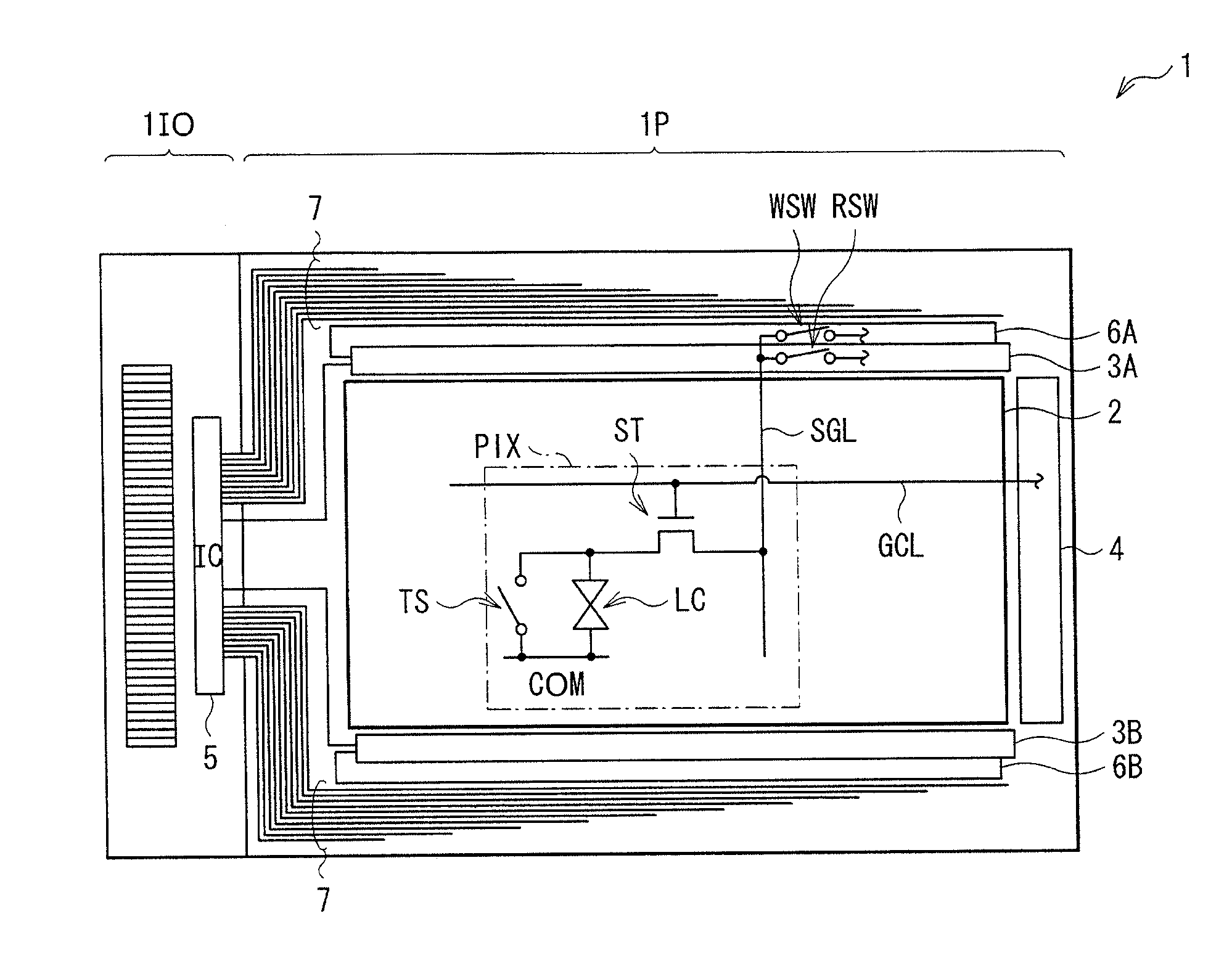
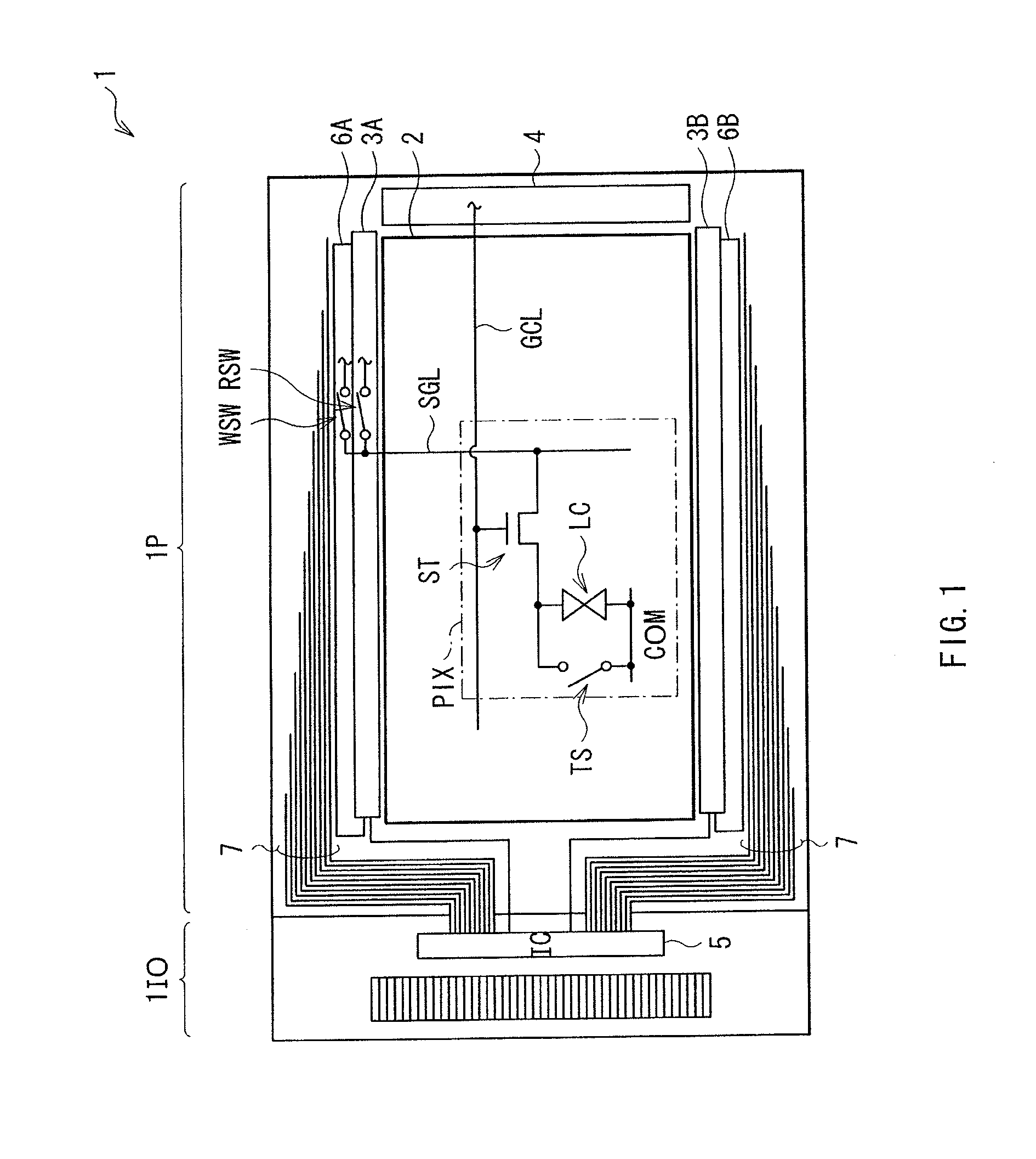
FIG. 1 illustrates a configuration example of a display according to a first embodiment of the invention. A display 1 is a so-called in-cell display in which a display panel and a touch panel are integrated into one unit, and is configured by using a liquid crystal element as a display element and a contact type touch sensor as a touch sensor element.

The display 1 includes a display panel 1P and a panel interface section 1IO. The display panel 1P is a liquid crystal display panel, and displays a picture based on a picture signal supplied through the panel interface section 1IO. In FIG. 1, a region illustrated as the display panel 1P corresponds to the size of a drive substrate. The display panel 1P includes a display section 2, source drivers 6A and 6B, sensor readout circuits 3A and 3B and a vertical drive circuit 4. In addition, hereinafter, the source drivers 6A and 6B and the sensor readout circuits 3A and 3B a...

modification example 1-1

(Modification Example 1-1)

Next, a display according to a modification example of the embodiment will be described below. The comparative example is a display 1S configured by using a display section in which lines are not shared between in the display operation and in the touch detection operation. In addition, substantially like components are denoted by like numerals as of the display 1 according to the embodiment and will not be further described.

FIG. 8 illustrates a configuration example of the display 1S according to the comparative example. The display 1S includes a display section 2S and a vertical drive circuit for sensor 4S.

The display section 2S includes a sensor line TSL, a gate control line for sensor GCL2 and a select transistor for sensor ST2. In the display section 2S, unlike the display section 2 (refer to FIG. 1), the touch sensor TS is configured separately from the liquid crystal element LC. In the select transistor for sensor ST2, one of a source and a drain is c...

second embodiment

2. Second Embodiment

Next, a display according to a second embodiment of the invention will be described below. A display 1A according to the embodiment is applied to a display performing a line inversion drive, and is allowed to perform a touch detection operation even in the case where the precharge operation is performed in an AC-like manner in response to a common drive signal COM. In addition, substantially like components are denoted by like numerals as of the display 1 according to the above-described embodiment and will not be further described.

Configuration Example

FIG. 9 illustrates a circuit configuration example of a sensor readout circuit 40 in the display according to the embodiment. The sensor readout circuit 40 includes an operation section 41.

The operation section 41 includes a plurality of readout transfer units 43 which are serially connected to one another. Each of the readout transfer units 43 includes an exclusive OR circuit (eor) XOR. A first input terminal of t...


PUM


Abstract

A display with a touch panel allowed to achieve high response performance while reducing power consumption is obtained. The display includes a plurality of display elements performing display based on picture signals supplied to a plurality of picture signal lines, respectively, a plurality of sensor elements outputting touch signals indicating detection of an external proximity object to a plurality of sensor signal lines (SGL), respectively, a detection section (a comparator 331) detecting each of the touch signals, a transfer output section (a D-type flip-flop 332 and an output buffer circuit 36) transferring and outputting a detection result of the detection section to outside, and a control section (a transistor switch SCW, a transfer clock control circuit 37 and a timing generator 35) controlling operations of the detection section and the transfer output section, allowing the transfer output section to operate in a case where the touch signal is detected in the detection section, and suspending an operation of the transfer output section in a case where the touch signal is not detected.

Description

TECHNICAL FIELDThe present invention relates to a touch panel detecting an external proximity object, a display and an electronic device including such a touch panel.BACKGROUND ARTIn recent years, attention has been given to a display in which a contact detection device so-called touch panel is mounted on a display such as a liquid crystal display and various buttons are displayed on the display so that information is allowed to be inputted by the buttons instead of normal buttons. In the display including such a touch panel, an input device such as a keyboard, a mouse or a keypad is not necessary, so there is a tendency to expand the use of the displays to portable information terminals such as cellular phones in addition to computers.On the other hand, a reduction in power consumption of various electronic devices attracts attention in response to recent interest in ecology. In the display including the touch panel, a reduction in power consumption of not only a display panel but ...

Claims


Application Information

Patent Timeline
IPC IPC(8): G06F3/045G09G3/36G09G3/30
CPCG02F2001/13456G06F1/3203G06F2203/04101G06F3/042G06F3/044G06F1/3262G06F3/0446G02F1/13456G02F1/13306G02F1/13338G06F3/0416
Inventor MIZUHASHI, HIROSHITAKAHASHI, YASUO
Owner JAPAN DISPLAY WEST
Why Eureka
Try Eureka