Timing signal processing apparatus for controlling driving of image-capturing element, and camera

a timing signal and image processing technology, applied in the field of cameras, can solve the problems of increasing the power consumption of the entire camera, affecting the image quality of the image,

Inactive Publication Date: 2007-02-15
CASIO COMPUTER CO LTD
View PDF4 Cites 36 Cited by
  • Summary
  • Abstract
  • Description
  • Claims
  • Application Information

AI Technical Summary

Benefits of technology

[0010] According to an aspect of the present invention, there is provided a camera which generates a timing signal for driving an image-capturing element and reads a pixel signal, comprising: an operation mode setting unit which sets one of a plurality of operation modes having different time periods necessary for reading an effective pixel signal for one frame at a time of successively reading pixel signals of a plurality of frames from the image-capturing element; a setting state control unit which causes the operation mode setting unit to set one of the operation modes, in which the time period necessary for reading the effective pixel signal for one frame is shorter; a discrimination unit which discriminates, in each of frame periods of the operation mode set by the setting state control unit, whether the timing signal is output during the time period necessary for reading the pixel signal for one frame; and a stopping unit which stops output of the timing signal to the image-capturing element in accordance with a discrimination result of the discrimination unit.

Problems solved by technology

In addition, with the provision of various functions such as an anti-shake function (correction of image distortion due to shaking of the hand), there is a tendency for the power consumption of the entire camera to increase.
Even in cases where the driving frequency is variable, the operation may become unstable when the driving frequency is dynamically varied.
Thus, if the driving frequency is lowered and the read time is increased as in the prior art, the image quality may deteriorate.

Method used


Image

  • Timing signal processing apparatus for controlling driving of image-capturing element, and camera
  • Timing signal processing apparatus for controlling driving of image-capturing element, and camera
  • Timing signal processing apparatus for controlling driving of image-capturing element, and camera

Examples


Embodiment Construction

[0027] An embodiment of the present invention will now be described with reference to the accompanying drawings.

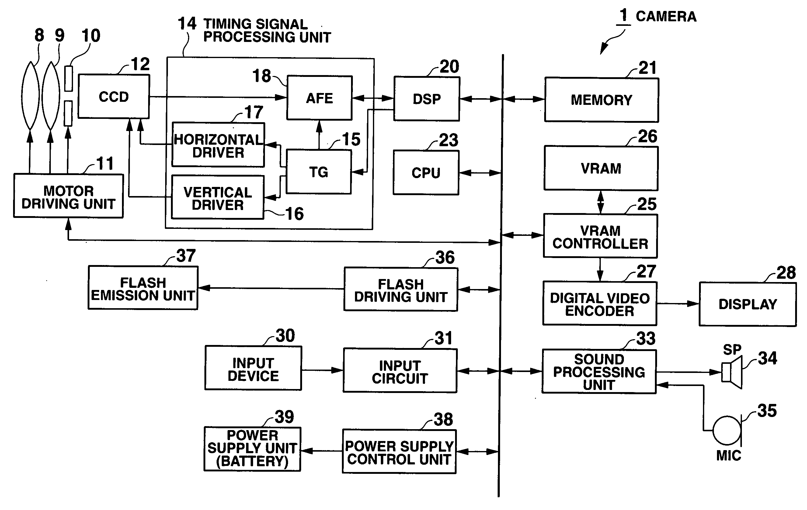
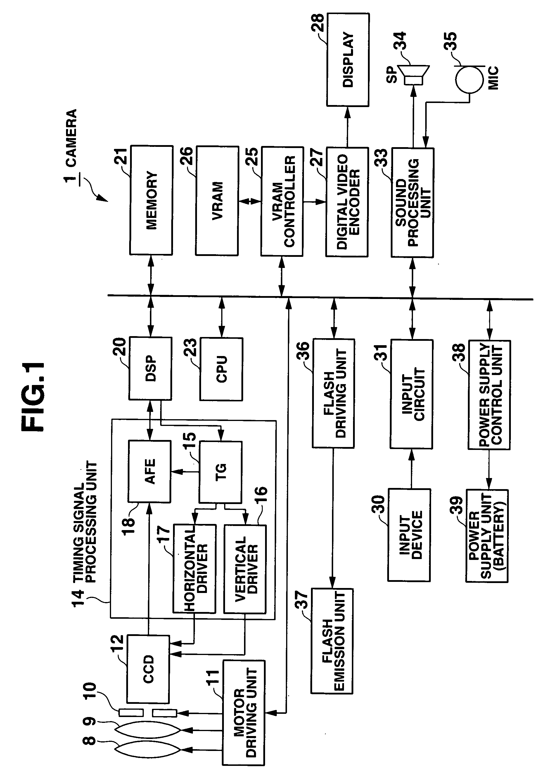
[0028]FIG. 1 is a block diagram showing the detailed structure of a camera 1 in the embodiment of the invention.

[0029] In the camera 1 shown in FIG. 1, in an image capturing mode that is the basic mode, a focusing lens 8, a zoom lens 9 and an aperture stop 10, which are included in a lens optical system, are shifted to lens positions and an aperture stop position according to image-capturing by a motor that is driven by a motor driving unit 11 under the control of a CPU 23.

[0030] A charge coupled device (CCD) 12, which is an image-capturing element disposed on a back side along the image-capturing optical axis of the lens optical system, accumulates a charge corresponding to an incident light amount on a pixel-by-pixel basis and is scan-driven by a signal from a timing signal processing unit 14. In every predetermined cycle, a pixel signal corresponding to a focused opt...


PUM


Abstract

A timing generator sets a 1-frame period, in which a pixel signal is read from a CCD, at a first period or a second period that is longer than the first period. The timing generator outputs specific timing signals (with optimal driving frequencies) to a vertical driver and a horizontal driver. If it is discriminated that the timing signal for a time period necessary for reading the pixel signal for one frame is output, the timing generator stops the output of the timing signal. Thereby, power saving can be achieved without deterioration of image quality, while reading of the pixel signal is being executed with an optimal driving frequency for the image-capturing element.

Description

CROSS-REFERENCE TO RELATED APPLICATIONS [0001] This application is based upon and claims the benefit of priority from prior Japanese Patent Application No. 2005-234570, filed Aug. 12, 2005, the entire contents of which are incorporated herein by reference. BACKGROUND OF THE INVENTION [0002] 1. Field of the Invention [0003] The present invention relates to a camera, such as a digital camera, a digital video camera or a camera-equipped mobile phone, which generates a timing signal for driving an image-capturing element and reads out a pixel signal, and a timing signal processing apparatus which generates a timing signal for use in the camera. [0004] 2. Description of the Related Art [0005] In recent years, with an increase in the number of pixels in cameras such as digital cameras, there is a tendency for higher power to be needed to drive an image-capturing element such as a charge-coupled device (CCD). In addition, with the provision of various functions such as an anti-shake functi...

Claims


Application Information

Patent Timeline
Patent Type & Authority Applications(United States)
IPC IPC(8): H04N5/335H04N5/341H04N5/347H04N5/353H04N5/3728H04N5/376H04N5/378
CPCH04N5/232H04N5/23245H04N5/23241H04N23/665H04N23/651H04N23/667
Inventor SUZUKI
Owner CASIO COMPUTER CO LTD
Why Eureka
Try Eureka