
Tire for heavy load use

a technology for heavy loads and tires, applied in the direction of tires without separate inflatable inserts, vehicle components, tire beads, etc., can solve the problems of deformation of the body, so as to prevent blowing by the carcass

Inactive Publication Date: 2006-03-14
SUMITOMO RUBBER IND LTD
View PDF3 Cites 6 Cited by
  • Summary
  • Abstract
  • Description
  • Claims
  • Application Information

AI Technical Summary

Benefits of technology

[0007]It is therefore an object of the present invention to provide a tire for heavy load use that is capable of improving binding force between a ply main portion and ply turn-up portions while securing advantages exhibited by the above bead structure, that is capable of restricting blow-by of the carcass, and that is capable of improving the durability of bead portions.
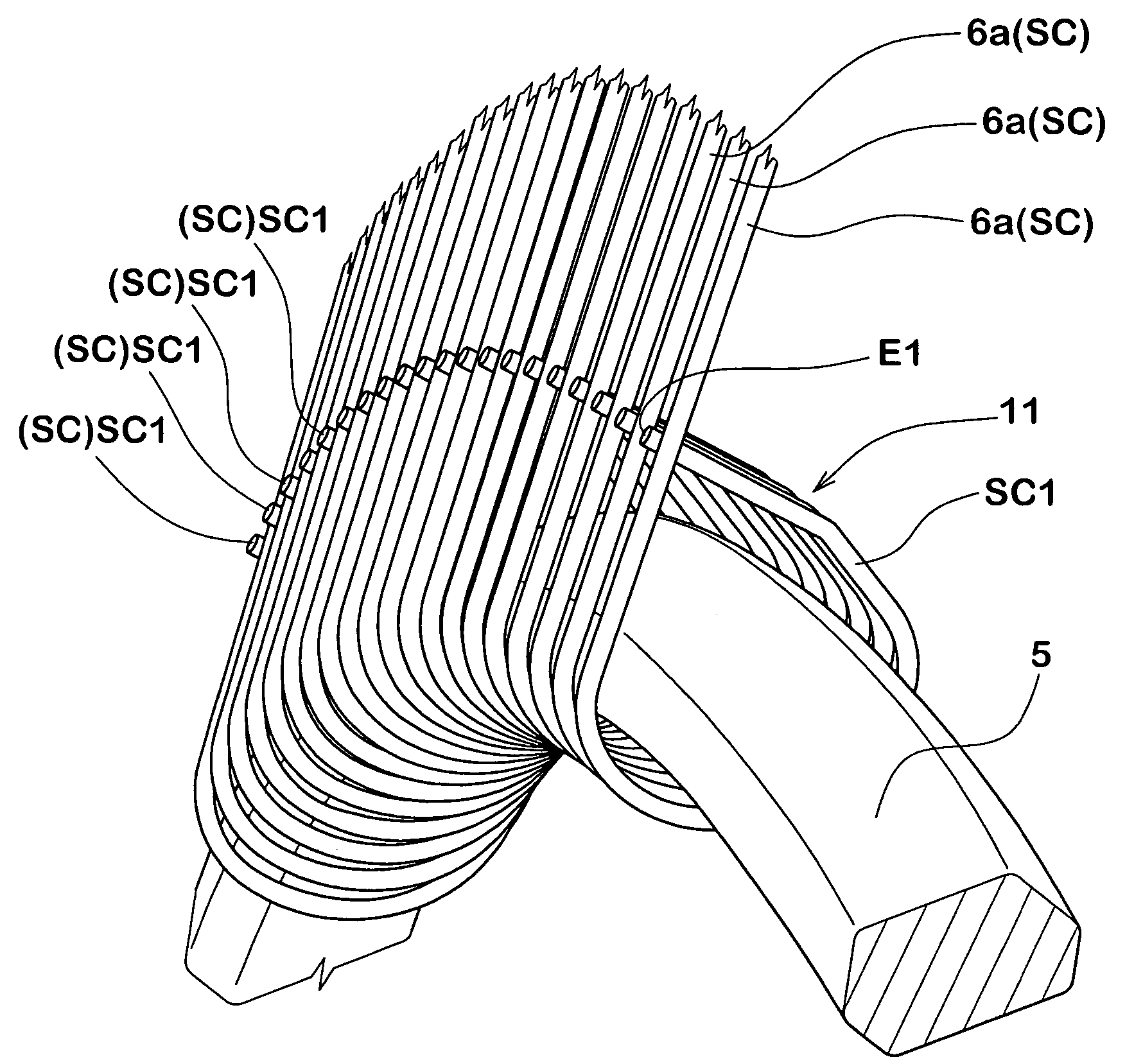
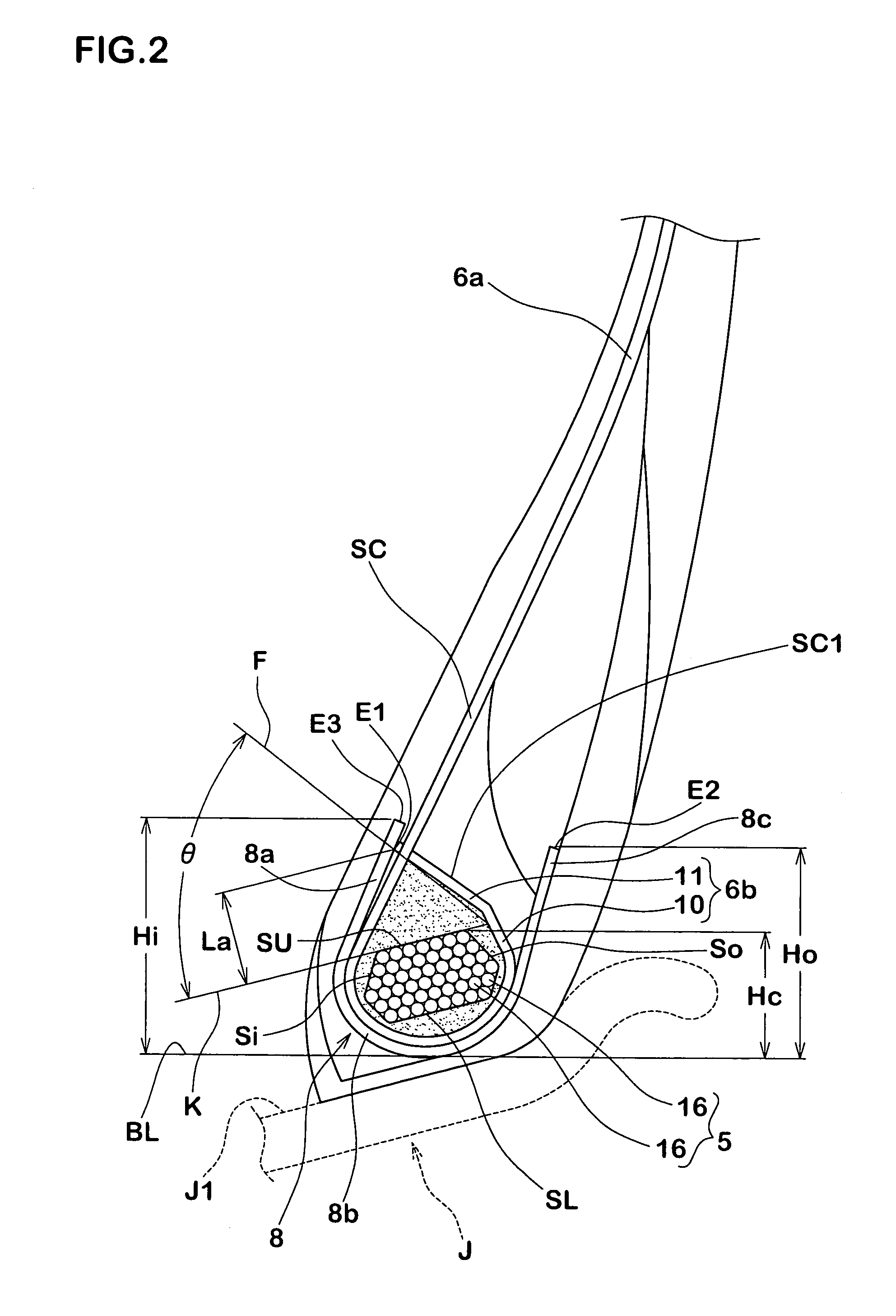
[0012]The tire for heavy load use of the present invention is arranged in that each turn-up sub-portion of the carcass ply terminates in a peripheral region of the bead cores that are exposed to small strains at the time of performing running under load conditions of the tire, thereby being hardly affected through strains during running. Moreover, the steel cords of the turn-up sub-portion include piercing steel cords that pass through the steel cords of the ply main portion. Since movements of the piercing steel cords are restricted between the steel cords of the ply main portion, it is possible to prevent blow-by of the carcass.

Problems solved by technology

Bead portions that bear a large amount of load are thus firmly reinforced, have a large thickness and also have an extremely large weight.
As a result, air holes are apt to be formed between the turn-up portions and the bead core c so that deficient moldings such as air residues are apt to occur.
Such deficient moldings present disadvantages in that engaging force proximate of the bead cores 5 of the carcass 6 is reduced so as to induce blow-by phenomena.

Method used


Image

  • Tire for heavy load use
  • Tire for heavy load use
  • Tire for heavy load use

Examples


examples

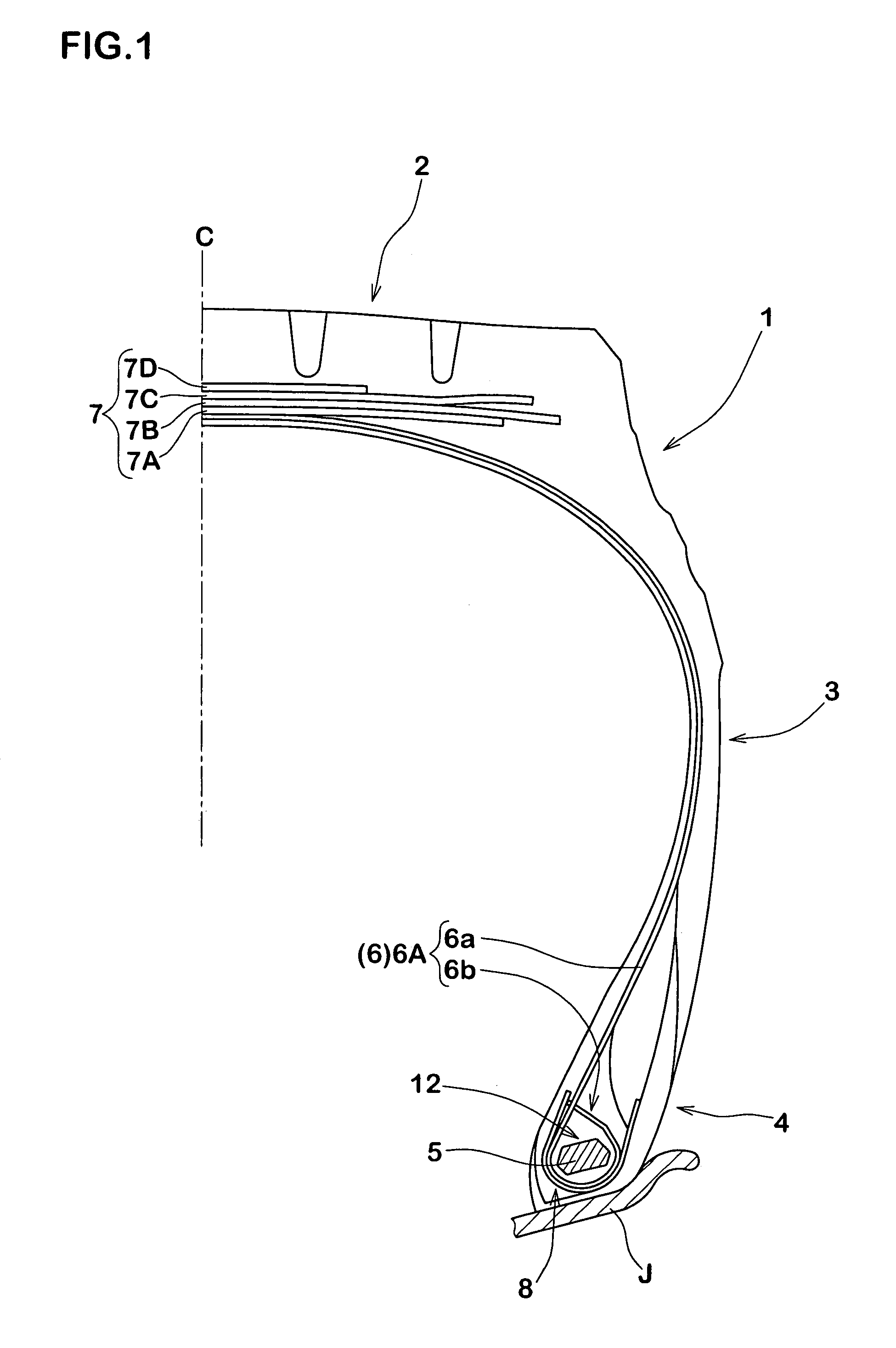
[0063]Tires for heavy load use having a basic structure of FIG. 1 and based on specifications as defined in Table 1 (size: 11R22.5, pattern: four ribs, groove depth: 14 mm, tread width: 230 mm, tread curvature radius: 700 mm) were sampled and measured for bead durability. The same tests were performed using a conventional tire as illustrated in FIG. 10 (Comparative Example 1) and a tire including no piercing steel cords while comprising the basic structure of FIG. 2 (Comparative Example 2) for comparing bead durability. In this respect, specifications not described in the tables were common to all tires, and the test methods were as follows.

[0064]A drum tester was employed for making the tires run under conditions for the rim being 7.50×22.5 for the rim, for that of the internal pressure 700 kPa and three times of 27.25 kN for the entire load at a velocity of 30 km / h, and the running times until damages were found at the bead portion were measured. Evaluations are indicated as indic...


PUM


Abstract

A tire for heavy load use includes a carcass ply made of steel cords including ply turn-up portions that are turned up around bead cores from inside to outside in a tire axial direction. Each ply turn-up portion includes a turn-up sub-portion that is first turned up around the bead core and that extends in an inclined manner towards the ply main portion at an angle θ, that is less than 90°, with respect to an outer surface of the bead core in the tire radial direction. The steel cords of the turn-up sub-portion include piercing steel cords that pass through the steel cords of the ply main portion. As a result, the durability of the bead portions is improved while achieving a light-weighted structure.

Description

BACKGROUND OF THE INVENTION[0001]1. Field of the Invention[0002]The present invention relates to a tire for heavy load use capable of improving the durability of bead portions.[0003]2. Description of the Prior Art[0004]A tire for heavy load use is filled with high air pressure and is used under demanding conditions of largely applied load. Bead portions that bear a large amount of load are thus firmly reinforced, have a large thickness and also have an extremely large weight. For reducing weights of such a tire for heavy load use, it has conventionally been suggested for a tire of bead structure as illustrated in FIG. 9 in which ply turn-up portions b2 that are wound around bead cores c by approximately a full round on both end portions of a main portion b1 of a carcass ply b extending between the bead cores c, c in JP-A 11-321244(1999) and JP-A 2000-219016.[0005]In such a bead structure, outer ends of the turn-up portions b2 are formed to be proximate to peripheries of the bead cor...

Claims


Application Information

Patent Timeline
Patent Type & Authority Patents(United States)
IPC IPC(8): B60C15/00B60C15/06
CPCB60C15/0027B60C15/06Y10T152/10828Y10T152/10819B60C15/0607
Inventor MARUOKA, KIYOTO
Owner SUMITOMO RUBBER IND LTD
Learn More