Method and apparatus for cooling electronic components

a technology of electronic components and cooling methods, applied in lighting and heating apparatus, process and machine control, instruments, etc., can solve the problems of difficult arrangement of air cooled machines in patterns, harsh environmental conditions, and impractical under-floor air flow rates

Inactive Publication Date: 2006-03-14
IBM CORP
View PDF13 Cites 110 Cited by
  • Summary
  • Abstract
  • Description
  • Claims
  • Application Information

AI Technical Summary

Problems solved by technology

As a result, sometimes it is difficult to arrange air cooled machines in patterns that will allow for effective cooling.
Other problems include impractical under-floor air flow rates, harsh environmental conditions, air conditioning power requirements, and the footprint of massive chillers.
Refrigeration is an expensive alternative, but can also have similar problems.

Method used


Image

  • Method and apparatus for cooling electronic components
  • Method and apparatus for cooling electronic components
  • Method and apparatus for cooling electronic components

Examples


Embodiment Construction

[0016]Disclosed herein is a liquid cooling mechanism for electronic and / or computer systems using fluid from a central supply. Embodiments hereof are configured as a modular cooling apparatus that can be easily installed and removed from a rack. Further, the disclosed modular cooling apparatus is stackable (either vertically or horizontally), i.e. it can be placed in a redundant configuration with another modular cooling apparatus. In such a redundant configuration, one of the modular cooling apparatuses can be shut down, while the other modular cooling apparatus remains in operation. This allows for the servicing or replacing of one of the cooling apparatuses, without the necessity of shutting down the electronic and / or computer system.

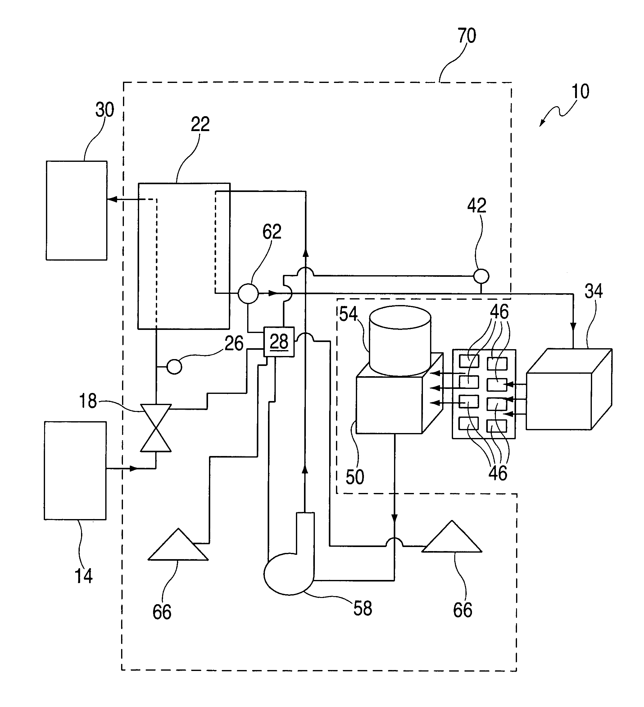
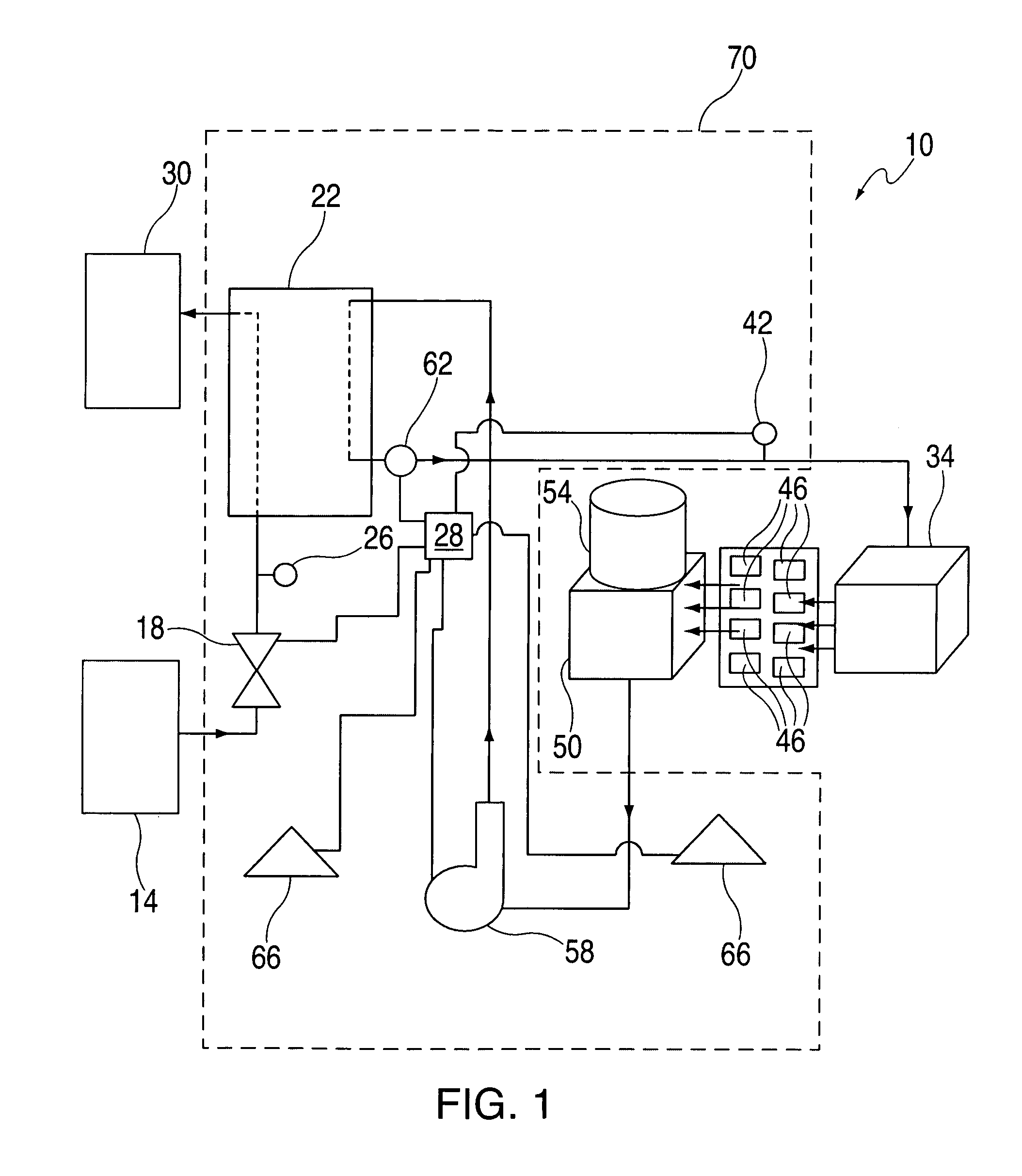
[0017]Referring to FIG. 1, a schematic diagram of an embodiment of a disclosed fluid cooling system 10 is shown. A first valve 18 is in fluid communication with a fluid supply 14 and in fluid communication with a heat exchanger 22. The first valve 18...


PUM


Abstract

A modular fluid unit for cooling heat sources located on a rack, the modular fluid unit comprising: a heat exchanger in fluid communication a pump; and wherein the modular fluid unit is mountable within the rack and is configurable to be in fluid communication with a cold plate return manifold, a cold plate supply manifold, and an end-user fluid supply. A method for cooling electronic components in a rack, the method comprising: circulating a first liquid from a cold plate to one of a plurality of heat exchangers mounted within the rack; circulating a second liquid from a second liquid supply to the one of a plurality of heat exchangers; and transferring heat from the first liquid to the second liquid at the one of a plurality of heat exchangers.

Description

BACKGROUND OF THE INVENTION[0001]The presently disclosed method and apparatus are generally directed to a cooling unit for the cooling of electronic components. More particularly, the disclosed method and apparatus are directed to a modular fluid cooling unit.[0002]One of the possibilities for cooling electronic components is the employment of arrays of air cooled heat sinks. Heat generated in an electronic component is conducted into the heat sinks and dissipated through the passage of a forced flow of ambient air within high aspect ratio flow channels between the heat sinks. Data centers with large computer and electronic systems vary greatly in airflow, raised floor height, chilled air availability and floor space. As a result, sometimes it is difficult to arrange air cooled machines in patterns that will allow for effective cooling. Each data center must be designed specifically to that data center's environmental conditions. In many cases, the machines must be spread out in ord...

Claims


Application Information

Patent Timeline
Patent Type & Authority Patents(United States)
IPC IPC(8): F28F7/00F23L15/02G06F1/20H05K7/20
CPCG06F1/20H05K7/20281G06F2200/201H05K7/20645H05K7/20781
Inventor CORRADO, JOSEPH P.EBERTH, JOHN F.MAZZUCA, STEVEN J.SCHMIDT, ROGER R.TSUKAMOTO, TAKESHI
Owner IBM CORP
Why Eureka
Try Eureka