Percussion tool and method

a technology of percussion instruments and percussion instruments, applied in the field of percussion instruments, can solve the problems of inability to achieve economic benefits, limited case studies, and failures, and achieve the effect of increasing the penetration rate of drilling and high vibration frequency

Inactive Publication Date: 2006-03-14
ASHMIN HLDG LLC
View PDF49 Cites 92 Cited by
  • Summary
  • Abstract
  • Description
  • Claims
  • Application Information

AI Technical Summary

Benefits of technology

[0016]The described percussion tool can be described more particularly, but not by way of limitation, as a percussion sub. An advantage of the presented percussion subs in drill strings will result in increase rates of drilling penetration. Another advantage is that the percussion sub may be used to free work strings that become stuck in a well. Still yet another advantage is that the percussion sub of the present invention can obtain very high vibration frequencies. For instance, frequencies of 20 Hz are possible.
[0017]Another advantage is that numerous configurations of the percussion sub are possible within a work string. For example, the percussion sub can be used in a drill string as an addition to existing drilling equipment; or the percussion sub used as a stand alone tool; or the percussion sub can be placed in more than one position in the drill string; or the percussion sub can be combined in series with more than one percussion subs. The percussion sub can also be an integral member of any other apparatus connected to a work string in order to function as a percussion tool.
[0018]Another advantage is that the percussion sub can also be used in a drill string with a rotary steerable assembly. Yet another advantage is that the percussion sub can be placed in a drill string having a motor or a turbine assembly. Still another advantage is that the percussion tool can be used to cement casing within a well bore.
[0020]Another feature is that the flow through the internal bore of the percussion sub activates the percussion sub. The flow stream can be a liquid, a gas, a liquid stream with solids, a gas stream with solids, or a mixture of liquids, gas and solids. Still yet another feature is that the operator can control the frequency of the hammer striking the anvil by varying the pumping rate, by varying the guide profiles, by varying the number of rotors, or by varying the rotor arrangement. Yet another feature is that the operator can control the amount of impact of the hammer striking the anvil by varying the mud weight, by varying the guide profiles, by varying the blade design, or by varying the rotor weight. Still yet another feature is that the percussion sub will continue vibrating despite flow streams containing high solids contents.

Problems solved by technology

However, those attempts have been largely case limited, non-economical, or unsuccessful.

Method used


Image

  • Percussion tool and method
  • Percussion tool and method
  • Percussion tool and method

Examples


Embodiment Construction

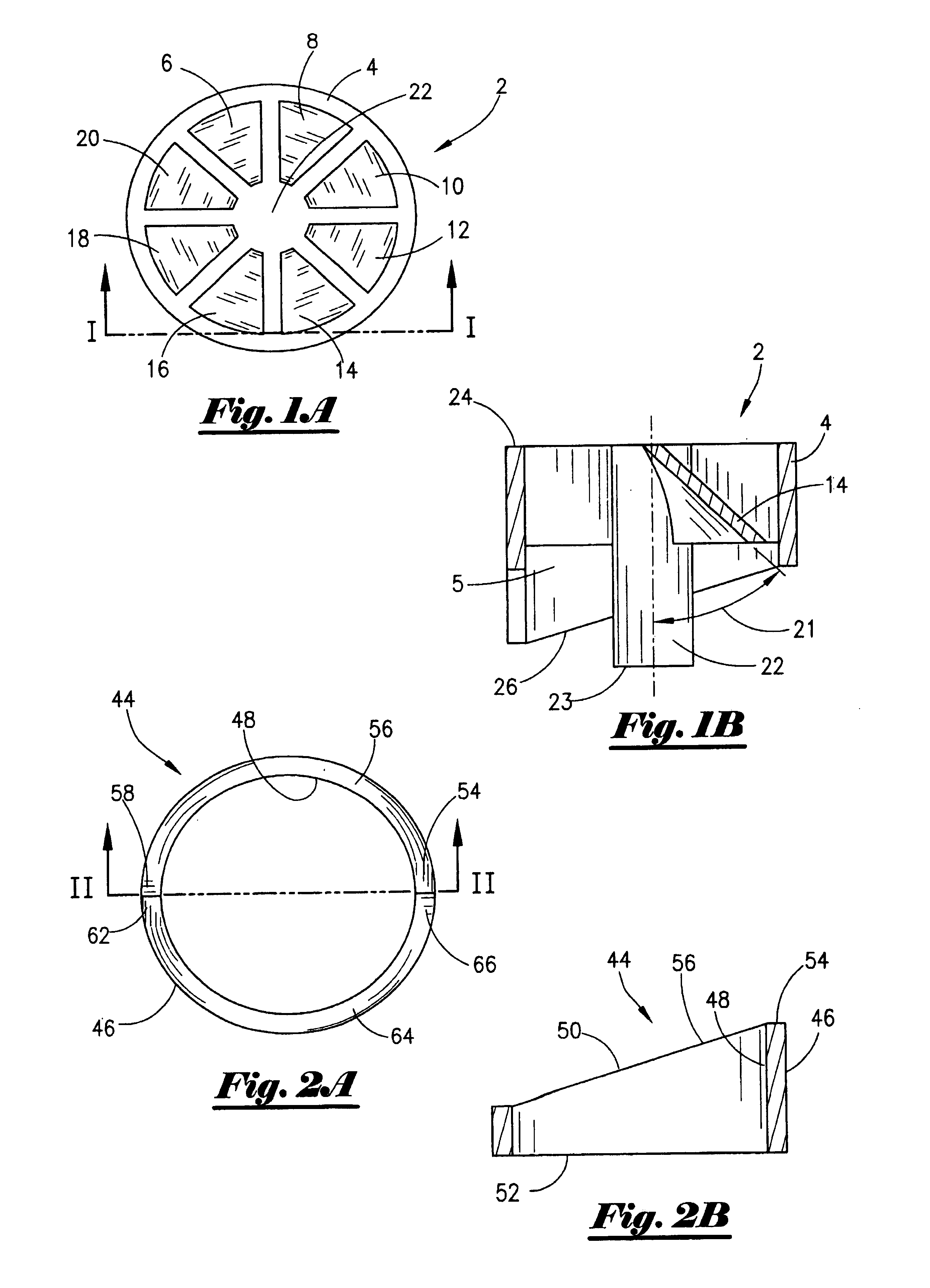
[0049]Referring to FIG. 1A, a top view of the rotor 2 of the present invention will now be described. The rotor 2 comprises a generally cylindrical member having an outer wall 4 that extends radially inward to the internal portion 5; the rotor 2 contains a plurality of blades within the internal portion 5 (seen in FIG. 1B). Returning to FIG. 1A, the blades 6, 8, 10, 12, 14, 16, 18, 20 emanate from a center core 22. The blades 6-20 are disposed with a certain angle or pitch, as will be fully set out later in the application.

[0050]In FIG. 1B, a cross-sectional view of the rotor 2 from FIG. 1A taken along line I—I will now be described. It should be noted that like numbers appearing in the various figures refer to like components. As illustrated in FIG. 1B, the internal portion 5 has the center core 22, with the center core 22 having extending therefrom the blade 14 extending to the outer wall 4. The blade 14 is attached at one end to the center core 22 and at the other end to the oute...


PUM

PropertyMeasurementUnit
angle of inclinationaaaaaaaaaa
frequenciesaaaaaaaaaa
angle of inclinationaaaaaaaaaa

Abstract

A percussion apparatus and method of using the percussion apparatus. The apparatus may be used for delivering an impact to a tubular string. The apparatus comprises a cylindrical member having an internal bore containing an anvil and a first guide profile. The apparatus further includes a rotor disposed within the internal bore, and wherein the rotor member comprises a body having an outer circumference with a second guide profile thereon, and wherein the rotor contains a radial hammer face. In a first position, the second external guide profile of the rotor will engage with the first guide profile of the cylindrical member so that the radial hammer face can contact the anvil. In a second position, the second guide profile of the rotor will engage with the first guide profile of the cylindrical member so that the radial hammer face is separated from the anvil shoulder. Multiple rotors and multiple stators may be employed. The rotor may be operatively associated with a stator that directs flow into the rotor. The rotor may be comprised of a plurality of inclined blades. The percussion apparatus may be incorporated into a tubular string and used for multiple purposes within a well bore. For instance, a method of cementing a well with the percussion apparatus is disclosed.

Description

BACKGROUND OF THE INVENTION[0001]This invention relates to a device and a method for delivering an impact or a force to a device. More particularly, but not by way of limitation, this invention relates to a percussion apparatus used with tubular members.[0002]Rotary bits are used to drill oil and gas well bores, as is very well understood by those of ordinary skill in the art. The monetary expenditures of drilling these wells, particularly in remote areas, can be a very significant investment. The daily rental rates for drilling rigs can range from a few thousands dollars to several hundreds of thousands of dollars. Therefore, operators have requested that the well bores be drilled quickly and efficiently.[0003]Prior art drill bits include, for Instance, the tri-cone rotary bit. The tri-cone bit has been used successfully for many years. The rock will be crashed by the impact of the tri-cone buttons. Also, the PDC bit (polycrystalline diamond compact bit) has been used with favorabl...

Claims


Application Information

Patent Timeline
Patent Type & Authority Patents(United States)
IPC IPC(8): E21B31/113B25D15/00E21B4/14E21B7/00B25D15/02
CPCE21B4/14
Inventor VON GYNZ-REKOWSKI, GUNTHER H H
Owner ASHMIN HLDG LLC
Why Eureka
Try Eureka