Bridging clutch for a hydrodynamic torque converter

a technology of hydrodynamic torque converter and bridging clutch, which is applied in the direction of rotary clutches, fluid couplings, gearings, etc., can solve the problems of narrowing down the outflow area and the inability of cool transport mediums to enter the inflow area of the opening, and achieves a high degree of energy efficiency and high efficiency. effect of uniform cooling

Inactive Publication Date: 2006-03-14
ZF FRIEDRICHSHAFEN AG
View PDF7 Cites 23 Cited by
  • Summary
  • Abstract
  • Description
  • Claims
  • Application Information

AI Technical Summary

Benefits of technology

[0011]In a first design, the friction lining carrier is provided with a recess, which is located in the area over which the opening in the friction lining extends and which, with respect to its geometry and its dimensions, essentially conforms to the opening in the friction lining. In this way, the thickness of the friction lining in the axial direction is added to the thickness of the friction lining carrier, so that a much deeper space is available for the formation of a vortex than would be the case if there were only a friction lining. Because the axis of rotation of the vortex extends essentially in the said axial direction of the friction lining carrier and the friction lining, it is possible in this way to obtain a vortex zone which is comparatively large in the axial direction and which contains a highly energetic vortex, as a result of which an intensive and simultaneously uniform heat exchange can be achieved. Of course, the effective height available to the vortex would be increased even more and thus the heat exchange made even more effective by the use of a plate with a friction lining carrier which has a friction lining on each side, the openings in the two friction linings being aligned not only with each other but also with the corresponding recess in the friction lining carrier.
[0012]According to another design, the friction lining carrier again has a recess located in the area over which the opening in one or both friction linings extends, but the dimensions of the recess in the friction lining carrier in this case are smaller than those of the openings in the friction linings. It is true that the resulting vortex, which is referred to below as the “main vortex”, will be smaller around the axis of rotation of the vortex than that which is formed in the previously described design, which means that the possibility for heat exchange is also reduced, but smaller “secondary vortices” will also form, especially on the side of the main vortex facing the associated outer contour of the opening. The axes of rotation of these secondary vortices will be essentially parallel to that of the main vortex, but they can be only as long as the depth of the associated friction lining in the axial direction. The secondary vortices can come into contact with large areas of the friction lining carrier, which, in contrast to the friction linings, is usually made of a material with good thermal conductivity, such as metal, and which therefore releases the heat it has absorbed from the friction linings very effectively to the adjacent secondary vortices.

Problems solved by technology

This vortex, however, at least narrows down the outflow area of the opening or possibly even blocks it completely.
The result is that heated transport medium present in the opening cannot leave the opening via the outflow area at a fast enough rate, and accordingly it is impossible for cool transport medium to enter at the inflow area of the opening.

Method used


Image

  • Bridging clutch for a hydrodynamic torque converter
  • Bridging clutch for a hydrodynamic torque converter
  • Bridging clutch for a hydrodynamic torque converter

Examples


Embodiment Construction

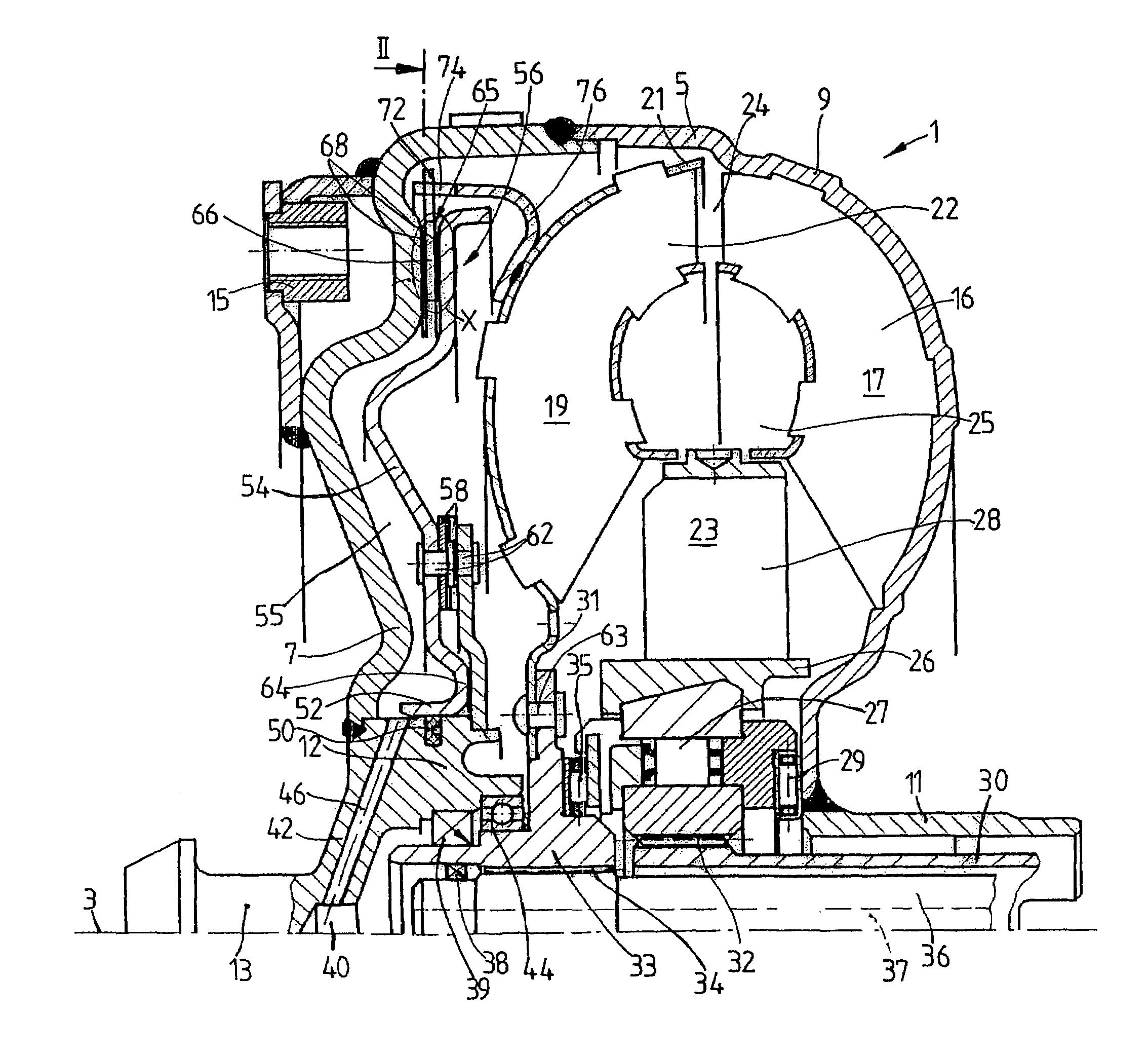
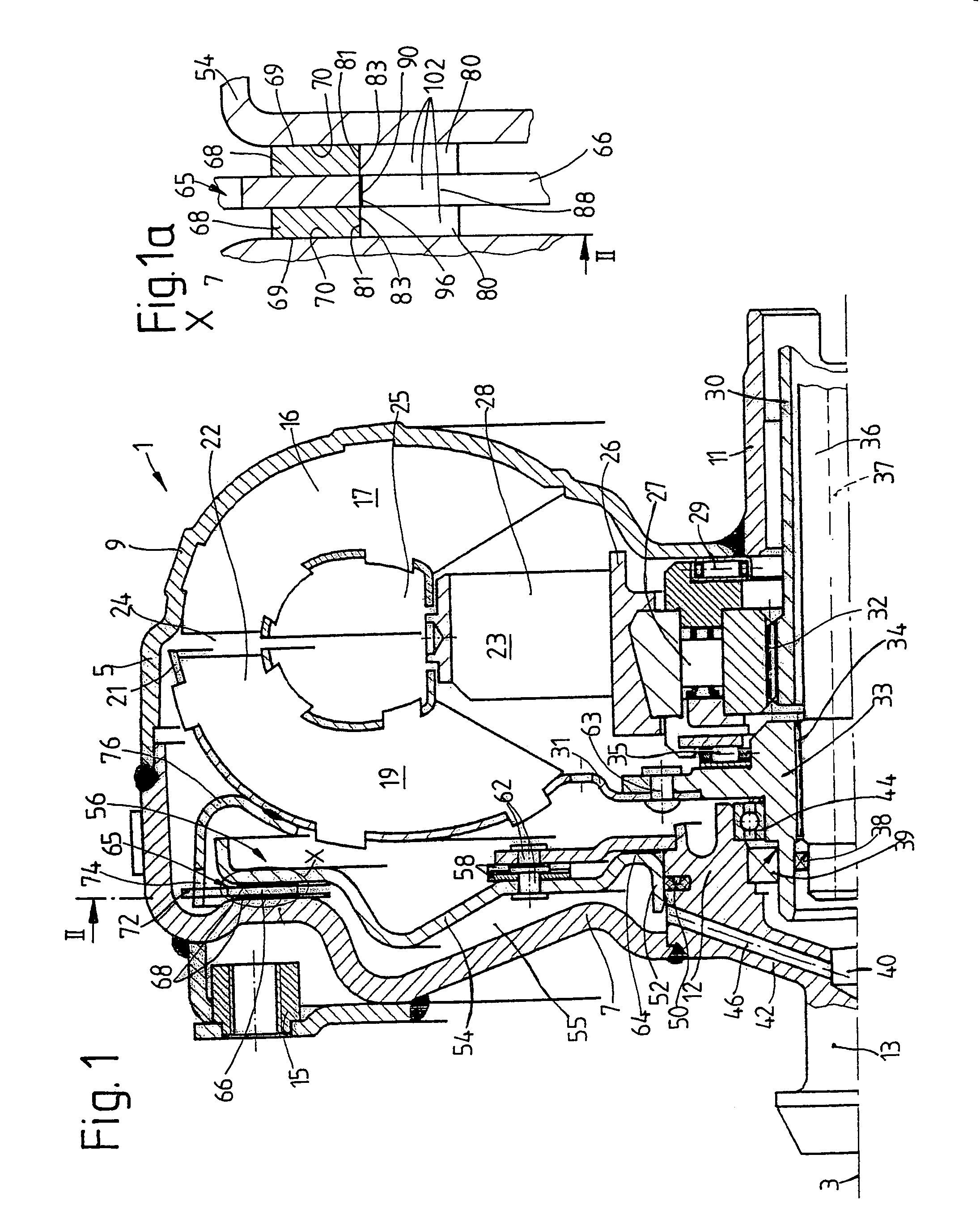
[0023]FIG. 1 shows a hydrodynamic torque converter 1, which is able to rotate around an axis of rotation 3. The hydrodynamic torque converter 1 has a converter housing 5, which has a converter cover 7 on the side facing a drive unit (not shown), such as an internal combustion engine. This cover is permanently connected to a pump wheel shell 9. In the radially inner area, this shell merges into a pump wheel hub 11.

[0024]To return to the converter cover 7, its radially inner area is provided with a journal hub 12 carrying a bearing journal 13. The bearing journal 13 is mounted on an element of the drive unit, such as a crankshaft, to center the converter housing 5 on the drive unit side. The method used to mount the journal is known in and of itself and is therefore not described in any further detail. The converter cover 7 also has a mounting receptacle 15, which usually serves to attach the converter housing 5 to the drive unit preferably by means of a flexplate (not shown). See, fo...


PUM


Abstract

A bridging clutch for a hydrodynamic torque converter which is designed with at least one friction area on a first converter component, which area can be shifted into working connection with at least one opposing friction area provided on a second converter component by means of an engaging movement or which can be separated from this second component by a disengaging movement in the direction opposite to the engaging movement. At least one of the two converter components acts as a friction lining carrier, which carries a friction lining in the friction area or in the opposing friction area, at least one opening being provided in the friction lining to allow the passage of transport medium, the inflow area of the opening being on the same radial side of the friction lining as its outflow area. On at least one of the converter components serving as a friction lining carrier, at least one friction lining is provided with an opening, which, on the radial side with the inflow area and the outflow area, is open continuously over its entire extent in the circumferential direction of the friction lining.

Description

BACKGROUND OF THE INVENTION[0001]1. Field of the Invention[0002]The invention pertains to a bridging clutch including a first converter component having a friction area and a friction lining carrier carrying a friction lining, wherein the friction lining and the friction area can be shifted into working connection by an engaging movement, the friction lining having radially inner side with at least one radially inward facing opening with an inflow area and an outflow area for the passage of transport medium.[0003]2. Description of the Related Art[0004]A bridging clutch for a hydrodynamic torque converter is known from U.S. 2003 / 010589. This bridging clutch has a piston, and as shown in FIG. 1, the side of this piston which faces the converter cover can be brought into working connection with a first friction lining, one side of which is attached to a plate connected nonrotatably to the turbine wheel of the torque converter. The plate carries on its opposite side, i.e., the side faci...

Claims


Application Information

Patent Timeline
Patent Type & Authority Patents(United States)
IPC IPC(8): F16H45/02
CPCF16H45/02F16H2045/0289F16H2045/0278F16H2045/0215
Inventor SUDAU, JORG
Owner ZF FRIEDRICHSHAFEN AG
Why Eureka
Try Eureka