

RF welding device
a welding device and rf technology, applied in the field of sealing devices, can solve the problems of material burning, poor quality, and shortening of other system components
- Summary
- Abstract
- Description
- Claims
- Application Information
AI Technical Summary
Benefits of technology
Problems solved by technology
Method used
Image

Examples
Embodiment Construction
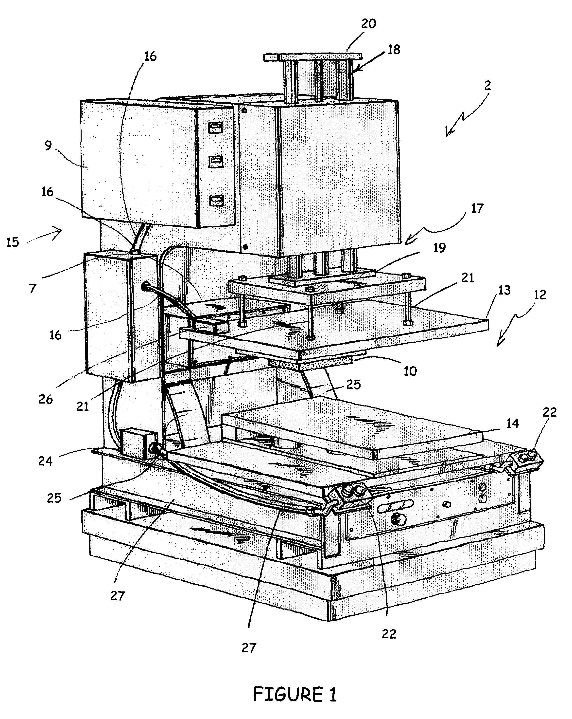
[0024]Turning to FIG. 1, an RF welder 6 is disclosed that has circuitry 7 and software that automatically tunes the impedance of the die 10 and material 11 (FIG. 3) to match that of a solid state generator 9. The tuning enables a maximum power transfer through the material 11.
[0025]Remaining with FIG. 1, the RF welder has welding components 12 that include a top platen or plate 13 and bottom plate 14. Each plate 13 and 14 is manufactured from an electrically conductive material and is adapted to act as an electrode for the RF a dielectric heating system. Each plate 13 and 14 is in communication with the high frequency RF generator 9 so that the top plate is electrically hot and the bottom plate serves as an electric ground.
[0026]The thickness of each plate is sufficient to prevent flexing or fatiguing of the plates by periodic loading of the plates. The top plate 13 is adapted to receive energy from the generator 9 and, as illustrated in FIG. 3, the bottom plate 14 is adapted to gro...
PUM
| Property | Measurement | Unit |
|---|---|---|
| frequency | aaaaa | aaaaa |
| resistance | aaaaa | aaaaa |
| resistance | aaaaa | aaaaa |
Abstract
Description
Claims
Application Information