Rearview mirror assembly with utility functions

a rearview mirror and utility function technology, applied in the field of rearview mirrors, can solve the problems of affecting the safety of the driver, so as to reduce the distraction caused by retrieval or placement in the storage space, facilitate access, and enhance the safety of the vehicle

Inactive Publication Date: 2006-03-14
DONNELLY CORP
View PDF98 Cites 208 Cited by
  • Summary
  • Abstract
  • Description
  • Claims
  • Application Information

AI Technical Summary

Benefits of technology

[0018]Advantages provided by the present invention include a high mounted storage location which is easily accessible to an occupant of the vehicle. In addition, by incorporating the storage space into an interior rearview mirror assembly the distraction caused by retrieval from or placem...

Problems solved by technology

As a result, many of these activities take the driver's attention away from the front of the vehicle because the activity involves the driver looking to locations in the vehicle remote from the windshield.
Furthermore, while note pad holder...

Method used


Image

  • Rearview mirror assembly with utility functions
  • Rearview mirror assembly with utility functions
  • Rearview mirror assembly with utility functions

Examples


first embodiment

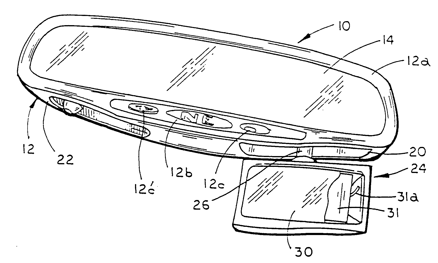
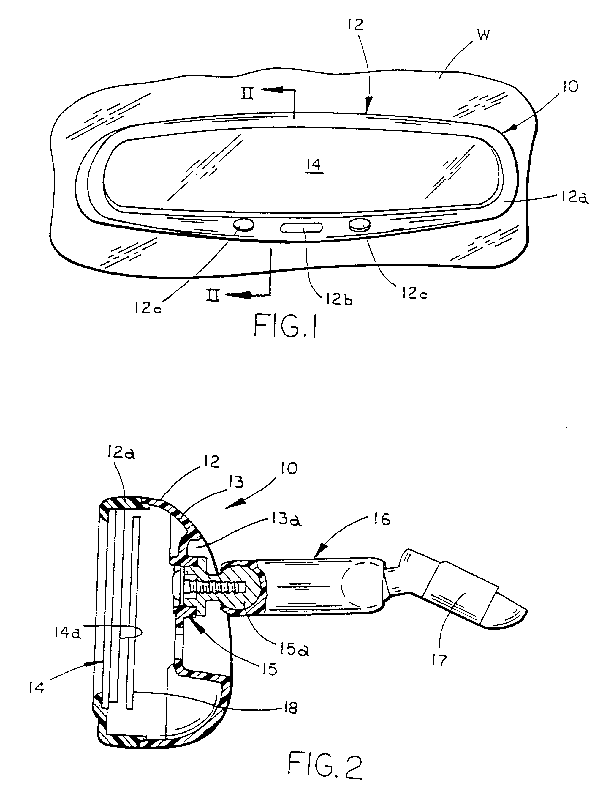
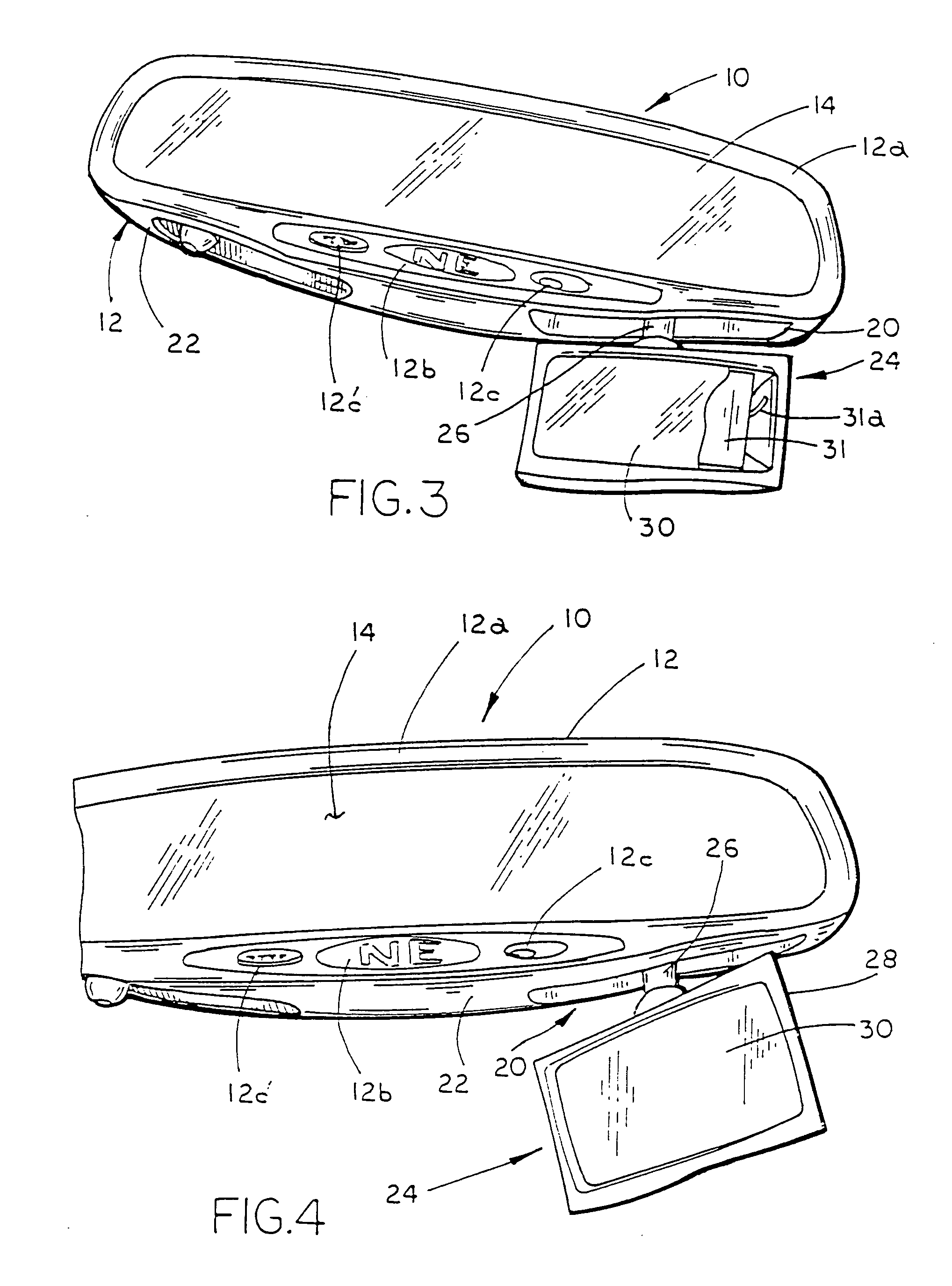
[0057]Referring to FIG. 1, the numeral 10 generally designates the interior rearview mirror assembly of the present invention. Assembly 10 is adapted to be releasably secured or coupled to the front windshield W of a vehicle in a conventional manner. Alternatively, assembly 10 can be adapted to secure or couple to the header portion of the vehicle above the windshield. Assembly 10 includes a mirror casing or housing 12 and a reflective element 14 which is supported in or on casing 12 in a conventional manner. Referring to FIG. 2, in the illustrated embodiment, mirror assembly 10 is mounted to windshield W by a support arm 16 and a break-away mounting bracket or mirror mount 17 which releasably mounts to a conventional mirror button on windshield W. Preferably support arm 16 is a conventional double ball type support arm which permits multi axis positioning of casing 12 about bracket 17. It should be understood that any suitable type of support arm may be employed for supporting mirr...

fourth embodiment

[0145]Referring to FIG. 33, the numeral 1610 generally designates the interior rearview mirror assembly illustrated in FIGS. 9–14. Mirror assembly 1610 includes a mirror housing or casing 1612, reflective element 1614, and a storage space 1622 for storing a dockable accessory 1624, similar to the previous embodiment. As previously described, dockable accessory 1624 may comprise a light assembly (shown), a telecommunications device, such as a phone or a pager or other hand held electrical or electronic devices. For further details of housing 1612, reflective element 1614 and accessory 1624, general reference is made to assembly 110.

[0146]Storage space 1622 is formed by a generally planar wall 1626 formed on back wall 1612a of casing 1612 and a generally open cavity 1628 which is formed in back wall 1612a and has a generally U-shaped configuration. Cavity 1628 is defined between planar wall 1626 and a generally U-shaped retaining wall 1628a which extends over planar wall 1626. Accesso...


PUM


Abstract

An interior rearview mirror assembly for a vehicle includes a reflective element, a housing or casing supporting the reflective element, and the casing including a storage space. The storage space provides storage for at least one accessory and for storing the accessory in the location easily accessible by an occupant of the vehicle whereby the accessory can be inserted into and removed from the storage space for use by an occupant of the vehicle. The storage space may take the form of a recess provided in a top wall of the casing, a recessed portion provided in a front wall, back wall, or end wall of the casing. In one form, the recessed portion houses a pendent accessory which is movable between a retracted position within the recess to an extended position for viewing by an occupant of the vehicle. For example, the pendent accessory may include a reflective element or a display element, for displaying information to an occupant of the vehicle.

Description

[0001]This application is a divisional application of U.S. patent application Ser. No. 10 / 207,291, filed Jul. 29, 2002 now abandoned, which is a divisional application of U.S. patent application Ser. No. 09 / 449,121, filed Nov. 24, 1999, by Applicants Barry W. Hutzel, Niall R. Lynam, Darryl P. DeWind, and John O. Lindahl, entitled “REARVIEW MIRROR ASSEMBLY WITH UTILITY FUNCTIONS”, now U.S. Pat. No. 6,428,172, the disclosure of which is herein incorporated by reference in its entirety.TECHNICAL FIELD AND BACKGROUND OF THE INVENTION[0002]The present invention relates to a rearview assembly and, more specifically to an interior rearview mirror assembly for use in vehicles incorporating utility functions, such as storage space for holding or housing various accessories.[0003]Until recently, rearview mirror assemblies have been used primarily for rear vision. More recently, electronic, electric and various additional functional features, however, have been added to the rearview mirror ass...

Claims


Application Information

Patent Timeline
IPC IPC(8): G02B7/182B60Q1/00B60R1/04G02F1/15G09F9/00B60R1/12B60R11/00B60R11/02G06Q20/00
CPCB60R1/12B60R11/02B60R11/0217B60R11/0247B60R2011/0033B60R2011/0026B60R11/0241
Inventor HUTZEL, BARRY W.LYNAM, NIALL R.DEWIND, DARRYL P.LINDAHL, JOHN O.
Owner DONNELLY CORP
Why Eureka
Try Eureka