Combined AC-DC to DC converter

a converter and ac-dc technology, applied in the direction of ac-dc conversion, electric variable regulation, ac-dc conversion, etc., can solve the problems of inability to perform a gradual switch of supply source without supply loss, inconvenience for the converter unit, etc., and achieve the effect of reducing the number of different converters and smallest possible number of components

Inactive Publication Date: 2006-03-14
AMERICAN POWER CONVERSION DENMARK
View PDF6 Cites 54 Cited by
  • Summary
  • Abstract
  • Description
  • Claims
  • Application Information

AI Technical Summary

Benefits of technology

[0013]The converter is characterized in that, on the basis of a signal from a current detector that measures the current through a coil, a control circuit has means for connecting and disconnecting, respectively, the one terminal of the coil to / from a DC supply source; and means to connect and disconnect, respectively, the second terminal of the coil to / from a common point of reference. The current through the coil flows to the DC output of the converter during periods when the second terminal of the coil is not connected to the common point of reference. The converter is provided with means for connecting and disconnecting, respectively, an AC supply source to the one terminal of the coil, ie that terminal on the coil that can also be connected to the DC source. A converter is obtained that has the smallest possible number of components and that is simultaneously capable of performing a gradual switch between supply sources; wherein the one supply source is an AC supply source; and the second supply source is a DC supply source. The converter protects against supply failures during abrupt switches between supply sources.
[0014]The converter is characterized in that at least one converter is used to form a DC output that is positive relative to a common point of reference; and at least one converter is used to form a DC output that is negative relative to a common point of reference. A converter is obtained that is able to deliver a positive, optionally more positive, DC output voltages, and one negative, optionally more negative DC output voltages that are protected against supply failures during abrupt switches between supply sources.
[0015]The converter is characterized in that the AC supply source is shared for the converters that are used to form a positive output voltage and the converters that are used to form a negative output voltage relative to a common point of reference. A converter is obtained that makes requirements to the smallest possible number of AC supply sources. This is a major advantage in that, thus, the converter can also be used where the availability of AC supply sources is scarce.
[0016]The converter is characterized in that the means for connecting and disconnecting, respectively, the one terminal of the coil to / from a DC supply source is a controllable switch. The controllable switch can be regulated to be connected for-at least a part of every other half-period. It is possible to regulate the period of time when supply is obtained from the DC supply source. This is associated with the advantage that it enables parallel coupling of a number of converters to the same battery. Each converter is then allocated a period of time that is different from that of the other converters, during which the converters obtain energy exclusively from the DC supply source. The option of parallel coupling converters to the same DC supply source also means that supply can be obtained by using as few DC sources as possible.
[0017]The converter is characterized in that the means for connecting and disconnecting, respectively, the second terminal of the coil to / from a common point of reference is a controllable switch. The controllable switch can be regulated to be connected for at least a part of every other half-period, and the controllable switch is typically connected in burst series. It is possible to regulate the voltage through the coil. On the one hand it makes it possible to perform a gradual switching in consumption of energy from the DC source, and on the other hand it makes it possible to adjust the nominal output voltage on the converter within a field. The option of adjusting the nominal output voltage of the converter within a field means that the same converter design can be used where there is a requirement for several different output voltages. Thereby the number of different converters can be reduced.
[0018]The converter is characterized in that semi-conducters are used as controllable switches comprising at least one of the types of field effect transistor, bipolar transistor, insulated Gate Bipolar Transistor (IGBT), Gate Turn-Off Tyristor (GTO) and Injection Enhanced Gate Transistor (IEGT). It is possible to select semi-conductor technology while taking into consideration requirements to supply, construction and space.

Problems solved by technology

The converter unit discussed in WO 0033451, however, presents an inconvenience because it cannot connect to an AC supply source.
Additionally, the converter unit is not capable of performing a gradual switch of supply source without supply loss, see the below description of a method.
Nor is the converter unit capable of performing an adaptive switch in case of overload situations.
As a result, the back-up supply time is longer than that of a conventional UPS system.
The ('564) system, however, is not capable of performing an uninterrupted switching between an AC supply source and a DC supply source.

Method used


Image

  • Combined AC-DC to DC converter
  • Combined AC-DC to DC converter
  • Combined AC-DC to DC converter

Examples


Embodiment Construction

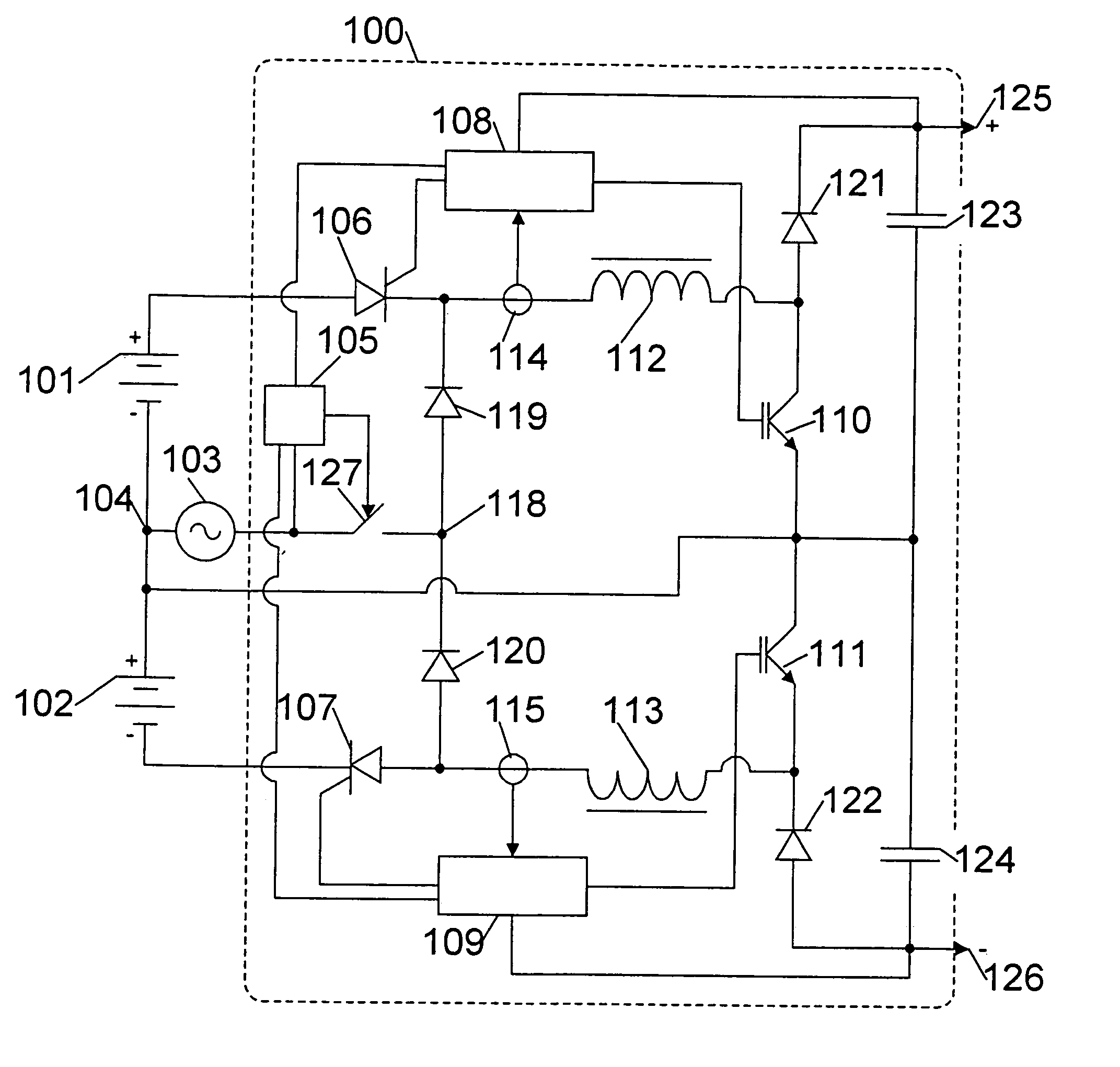
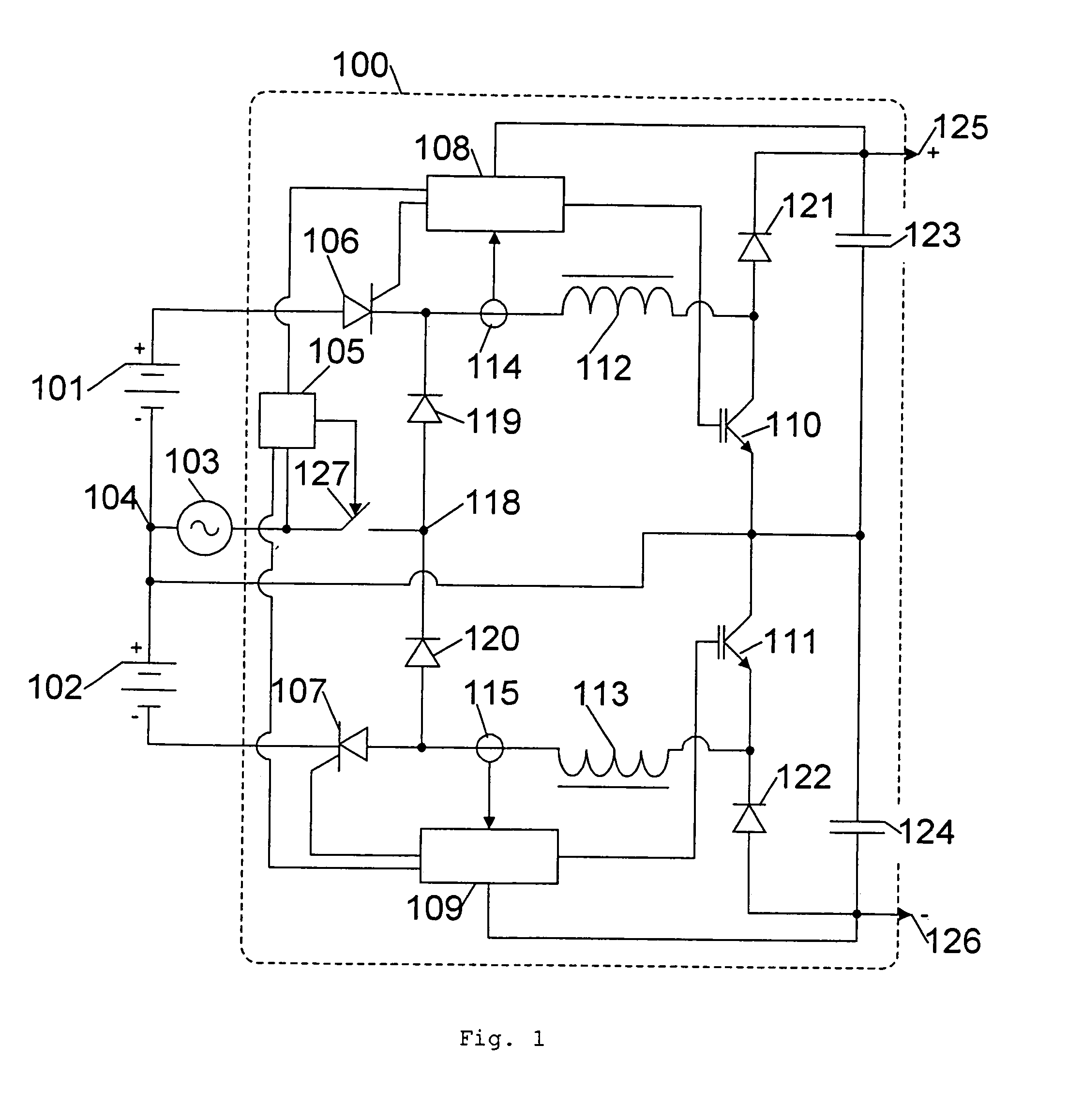
[0028]FIG. 1 shows a single-phase combined AC-DC to DC converter 100 with positive as well as negative output voltage. The positive terminal on a battery 101 is connected to the anode on a tyristor 106. The negative terminal on the battery 101 is connected to a common point of reference 104. The cathode on the tyristor 106 is connected to the cathode on a diode 119. The gate on the tyristor 106 is connected to an output on a control circuit 108. The cathode on the tyristor 106 is connected to a coil 112. A current sensor 114 encloses the connection between the tyristor 106 and the coil 112. The current sensor 114 is connected to an input on the control circuit 108. The coil 112 is further connected to collector on a transistor 110. Collector on the transistor 110 is connected to the anode on a diode 121. Emitter on the transistor 110 is connected to the common point of reference 104. An output on the control circuit 108 is connected to the base of the transistor 110. The cathode on ...


PUM


Abstract

The invention relates to a combined AC-DC to DC converter. The converter provides the option of coupling to an AC supply source with at least one phase and the further option of coupling to at least one DC supply source. The converter obtains supply from at least one supply source at a time; and the converter contains controllable contact means that are, upon switching between supply sources, capable of connecting and disconnecting the individual supply sources to/from the converter; whereby a pulse signal is generated. The converter contains at least one coil that is in connection with at least one DC output. The proposed converter distinguishes itself over the prior art in that switching between supply sources is accomplished by means of the contact means over a period of time, where the pulse signal is divided into periods; and wherein the periods alternatingly originate from at least one first supply source and at least one second supply source; and wherein the current pulses from the first supply source is regulated in dependence on the current pulses from the second supply source; and wherein the converter contains means for voltage regulating at least one DC output. Hereby a flexible converter is obtained that can obtain supply from an AC supply source and one or more DC supply sources; and wherein switching between a first supply source and a second supply source can be accomplished without supply failures; and wherein, in overload situations, it is possible to draw on two or more supply sources.

Description

CROSS-REFERENCE TO RELATED APPLICATION[0001]This application is the National Stage of International Application No. PCT / DK02 / 0004, filed 22 Jan. 2002.FIELD OF THE INVENTION[0002]The invention relates to a combined AC-DC to DC-converter. The converter provides at least one DC output from at least one AC supply with at least one phase and at least one DC supply. The AC supply supplies an AC signal comprising positive and negative half-periods. The converter comprises at least one coil that is in connection with the DC output. The converter contains controllable contact means adapted for connecting and disconnecting the AC supply and the DC supply to and from the converter.BACKGROUND[0003]Patent application No. WO 0033451 teaches a converter unit for converting two or more DC voltage levels from the input of the converter unit to a DC voltage on the output of the converter unit, wherein the converter unit comprises controllable switch means that are able to connect and disconnect the i...

Claims


Application Information

Patent Timeline
Patent Type & Authority Patents(United States)
IPC IPC(8): H02M1/10H02J9/06H02M3/155
CPCH02M1/10H02J9/062
Inventor NIELSEN, HENNING ROAR
Owner AMERICAN POWER CONVERSION DENMARK
Why Eureka
Try Eureka