Vent plug system for storage batteries

a technology of storage batteries and vent plugs, which is applied in the direction of gastight accumulators, secondary cell gas removal, electrical equipment, etc., can solve the problems of complex assembly, device and its assembly is uneconomical, and individual components must be fabricated within very stringent tolerances, so as to achieve significant cost-effectiveness, less stringent tolerance requirements, and cost-saving

Inactive Publication Date: 2005-01-18
ACCUMULATORENWERK HOPPECKE
View PDF62 Cites 10 Cited by
  • Summary
  • Abstract
  • Description
  • Claims
  • Application Information

AI Technical Summary

Benefits of technology

This invention to introduce an improved vent plug system of the type described whereby, without the need for excessive production tolerances, the smallest possible number of components can be combined, easily, cost-effectively and with a minimum of assembly operations, into a system that ensures reliable operation. As an overall requirement, this improved vent plug design is intended to reduce the cost involved in producing the system.
With industrially mass-produced elements of this nature, even minute simplifications in the fabrication and assembly of their components add up to substantial, significant cost savings.
According to the invention, the inner cartridge is provided with an installation fitting by means of which it is possible to position the plug element in simple fashion and without compromising it due to any pressure applied during the assembly, to position the inner cartridge appropriately and, applying a certain force, to mount it along a specific path in a defined position relative to the plug element, with the installation fitting being the only point where force is applied. When the system is properly assembled, the installation fitting protrudes from the plug element. While this makes the axial length of the plug element slightly longer, the advantages derived in the fabrication and assembly make up for that. This protrusion is minor and does not negatively affect universal suitability of the vent plug system.
The solution per this invention involves only three components that must be produced separately and may be individually varied depending on their intended functionalities. These three components are positioned in alignment with one another and then secured in place. By virtue of an installation fitting on the inner cartridge, which, when installed, protrudes axially from the plug element, it is possible to implement a gas-tight connection between the inner cartridge and the plug element around the lower end faces of both elements. According to one advantageous provision of the invention, the two elements, i.e. the plug element and the inner cartridge, are welded together in the area of their lower end faces. In particularly desirable fashion the installation fitting is annular in design and concentrically surrounded by an outer ring which, after the inner cartridge has been installed in the plug element, is fused onto the end face of, and thus welded onto, the plug element. A design of this nature further reduces the tolerance requirements in production. Welded together in the area of their mating circumferential surfaces, the inner cartridge and the plug element are thus connected in gas-tight fashion, while the actual functional surfaces of the plug element, meaning the gas passage and the valve-element backstop on the end face of the inner cartridge inserted in the plug element, are unaffected by this connection.
What is important is that the force applied when the inner cartridge is inserted allows axially straight insertion of the cartridge in the plug element and that the weldment on the perimeter ensures an adequately strong and gas-tight connection with the end face of the plug element.
This invention permits substantial cost savings in the production and assembly of the individual components of a vent plug system, the result being not only significant cost-effectiveness but technical simplification as well especially in terms of less stringent tolerance requirements and the assembly process in general, given that no special assembly tools or procedures are necessary.

Problems solved by technology

The individual components must be fabricated within very stringent tolerances and involve complex assembly since the insert can be forced in only to where it is flush with the plug element.
This makes the device and its assembly an uneconomical proposition.
Yet if in the said flush position the contact needed for the operation of the valve is not attained, the valve element is not properly positioned and its functionality is no longer assured.
Also, forcing the insert into the plug element involves mechanical impact on the plug element which can easily cause damage to its lower, open end face.

Method used


Image

  • Vent plug system for storage batteries
  • Vent plug system for storage batteries
  • Vent plug system for storage batteries

Examples


Embodiment Construction

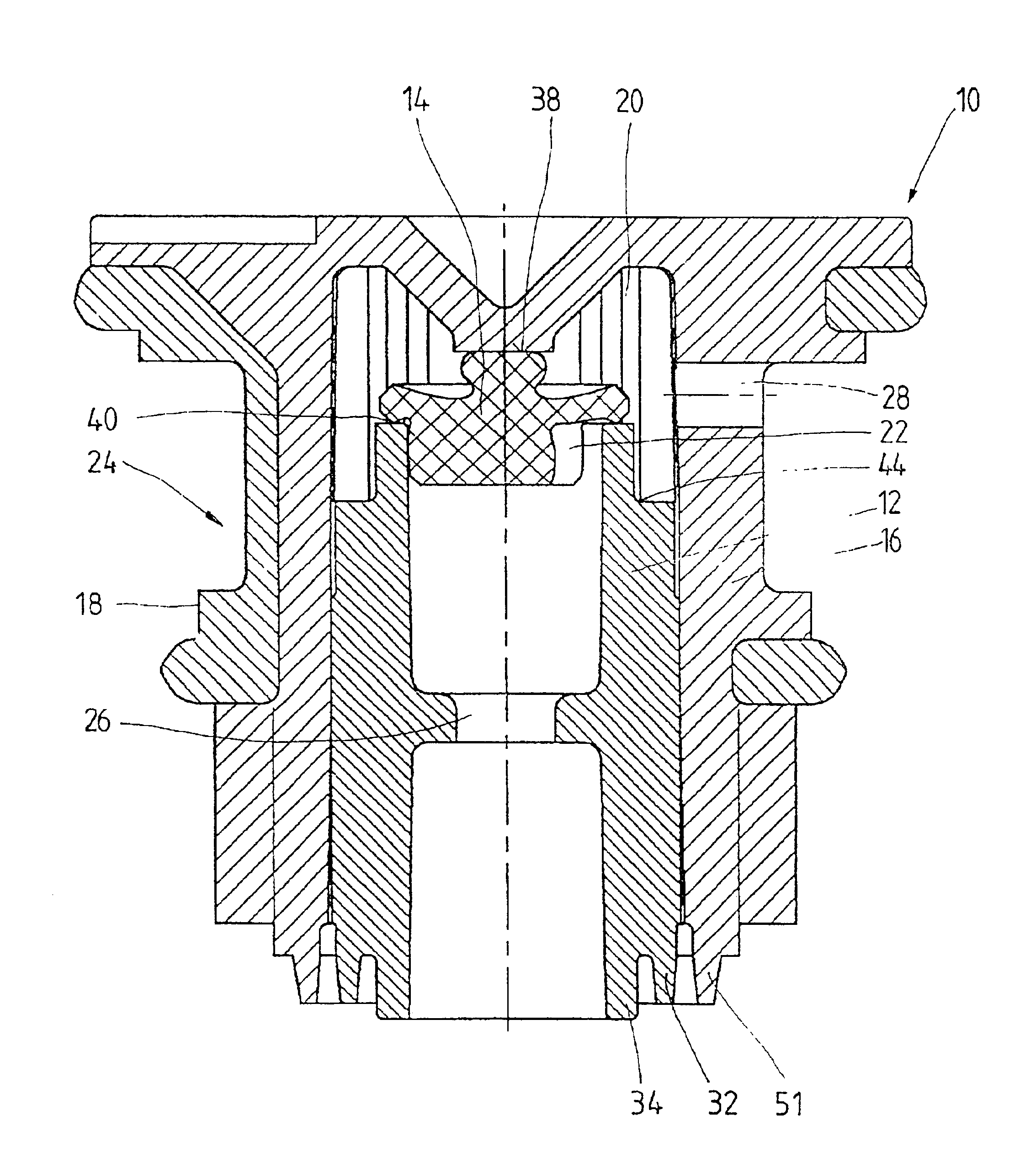
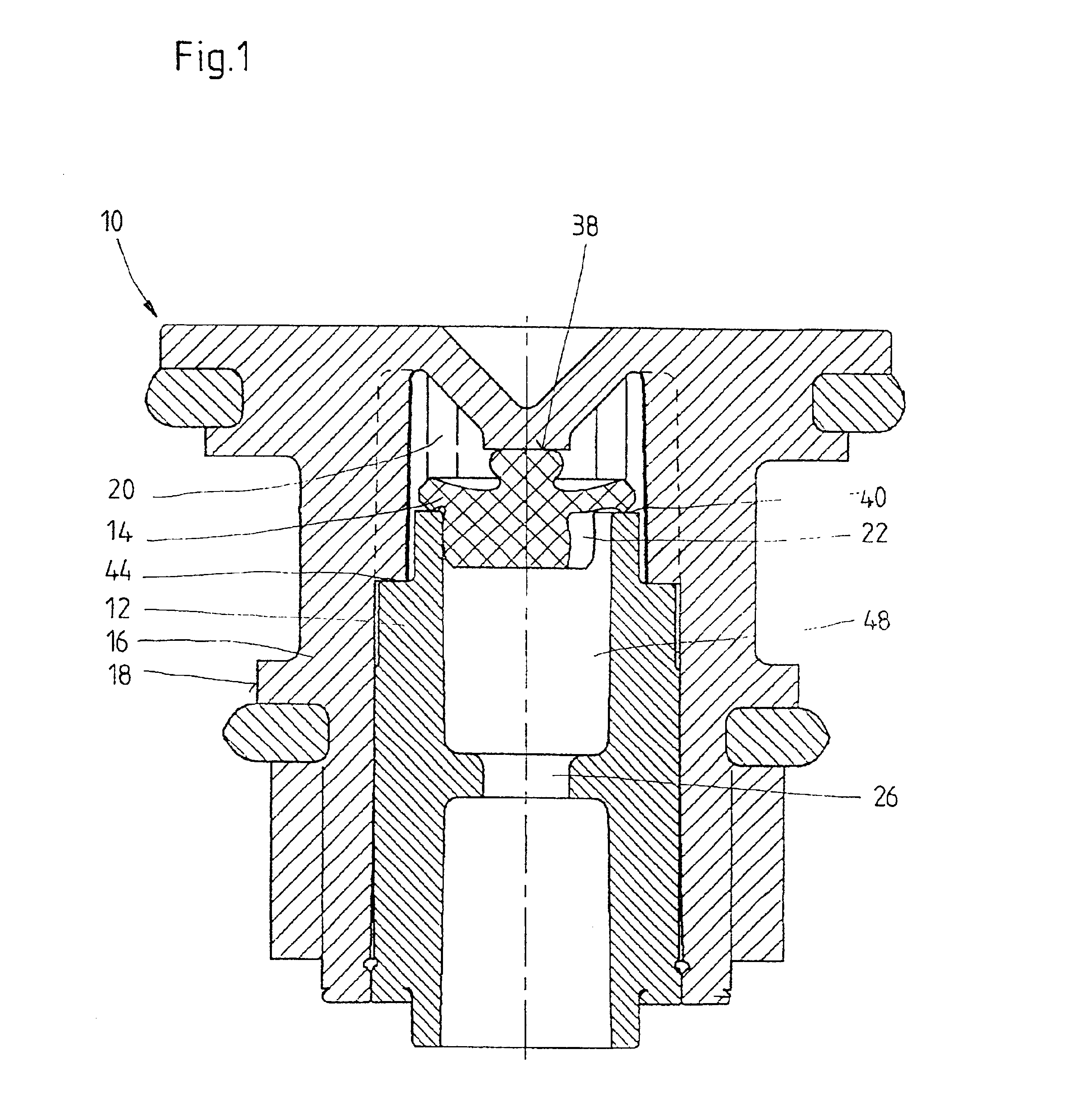
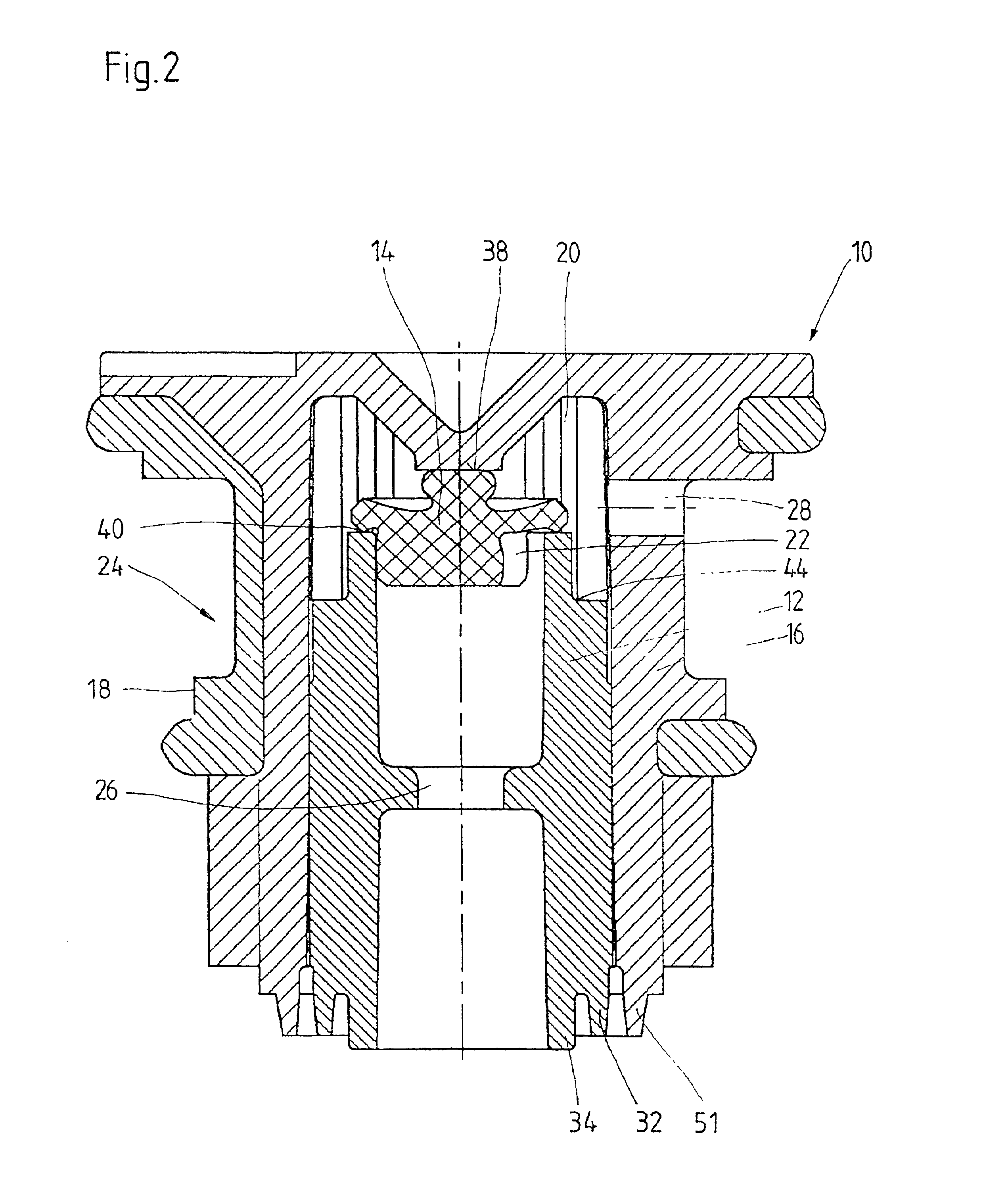
FIG. 1 illustrates a vent plug system 10 for the cell opening of a storage battery, not shown, with a plug element 16 incorporating an inner cartridge 12 and a valve element 14. The plug element 16 is cup-shaped, with an outer contour 18 adapted for insertion in and sealing of the cell opening, an internal cavity 20 and a gas port 28 between the cavity 20 and the outside surface 24 (FIG. 2). The inner cartridge 12 is cylindrical, with an outer contour 36 (FIG. 3) matching the shape of the cavity 20 of the plug element 16, and with a gas passage 26 that opens into the cavity 20.

The valve element 14 is designed as a separate entity held in place in the cavity 20 by the inner cartridge 12. As a function of the gas pressure, it establishes a gas-flow connection 22 between the gas passage 26 of the inner cartridge 12 and the gas port 28 of the plug element 16.

The inner cartridge 12 and the plug element 16 are joined in gas-tight fashion. When the inner cartridge is installed, an installa...


PUM

PropertyMeasurementUnit
pressureaaaaaaaaaa
pressure-responsiveaaaaaaaaaa
surface areasaaaaaaaaaa

Abstract

To improve on a vent plug system for a cell opening of a storage battery containing a plug element with an inner cartridge and a valve element, to where it is possible without the need for maintaining excessive physical tolerances to assemble it with a minimal number of components m simple fashion while still assuring reliable operation without any major effort, the plug element is provided as a cup-shaped unit with an outer contour shaped to fit into, and seal, the cell opening, with an internal cavity and with a gas port between the cavity and an outside surface. The inner cartridge is essentially cylindrical, has an outer contour shaped to permit insertion in the cavity of the plug element and is provided with a gas passage that opens into the cavity, while the valve element is a separate element retainable in the cavity by the inner cartridge and, as a function of the gas pressure, establishes a gas-flow connection between the gas passage of the inner cartridge and the gas port of the plug element. The inner cartridge and the plug element can be joined in gas-tight fashion, and the inner cartridge features an installation fitting which in the assembled state of the system protrudes at least partially from the cavity of the plug element.

Description

FIELD OF THE INVENTIONThis invention relates to a vent plug system for the cell opening of a storage battery, with a plug element incorporating an inner cartridge and a valve element.DESCRIPTION OF THE RELATED ARTSimilar plug systems have been known in prior art. The individual cells especially of recombination-type storage batteries have openings, usually threaded, and the pressure-activated valve permits the bleeding-off of built-up gases while preventing leakage or evaporation and, conversely, the undesirable entry of the outside atmosphere into the battery cell.U.S. Pat. No. 4,052,534 describes a plug system in which a cup-shaped plug element serves to accommodate an elastic, slotted valve plate and an insert supporting the valve plate, both held by an additional cartridge which is itself connected to the plug element. A similar system is also described in DE 40 32 858, where, in addition to the aforementioned components such as the plug element, insert, valve plate and cartridg...

Claims


Application Information

Patent Timeline
Patent Type & Authority Patents(United States)
IPC IPC(8): H01M2/12
CPCH01M2/1205H01M2/1229Y02E60/10H01M50/308H01M50/325
Inventor CRAMER, WILHELMNANN, EBERHARDHULSCHER, MANFRED
Owner ACCUMULATORENWERK HOPPECKE
Why Eureka
Try Eureka