Vehicle brake control apparatus

a technology of brake control and brake pedal, which is applied in the direction of brake components, failure-safe aspects, braking systems, etc., can solve the problems of excessive motor electric current, rush current, and inability of electric parking brake apparatus to generate braking force at both rear wheels

Active Publication Date: 2020-10-13
TOYOTA JIDOSHA KK
View PDF18 Cites 0 Cited by
  • Summary
  • Abstract
  • Description
  • Claims
  • Application Information

AI Technical Summary

Benefits of technology

[0009]In view of the forgoing, one object of the present disclosure is to provide a vehicle brake control apparatus configured to be able to avoid occurrence of the temporary failure of power supply and to prevent the increase in the braking distance as much as possible, even when the hydraulic brake apparatus fails during execution of the EPB stop process.
[0032]Therefore, according to the apparatus of the present disclosure, when the hydraulic brake apparatus fails while the EPB stop process is being executed, braking distance can be prevented from increasing as much as possible because the electric parking brake apparatus starts generating braking force. In addition, according to the apparatus of the present disclosure, the temporary failure of power supply can be avoided, since the sequential brake process is executed when the electric parking brake apparatus starts generating the braking force.
[0041]Accordingly, deflection of braking force in the lateral direction (in the right and left direction) of the vehicle is reduced / smaller as compared to a case where braking force is generated only at wheels either in the right side or in the left side, whereby a likelihood that a direction of the vehicle (namely, a yaw angle of the vehicle) changes can be reduced. Hereinafter, a phenomenon that the direction of the vehicle changes due to the deflection of braking force in the lateral direction of the vehicle will also be referred to as a “vehicle deflection phenomenon.” Namely, according to the present aspect, the likelihood that the vehicle deflection phenomenon occurs when the specific brake process is being executed can be reduced.
[0043]According to the above aspect, if one of the front wheels is the specific brake wheel, braking force is generated at this front wheel (the specific brake wheel) and at one of the rear wheels (the preceding brake wheel, which is opposing to the specific brake wheel in the lateral direction), during the time period from the time point at which the specific brake process is started to the time point at which the predetermined time period elapses. In this case, a “possibility that driving stability of the vehicle is improved when a disturbance occurs (for example, strong crosswind which blows on the vehicle, and traveling of the vehicle into a puddle of water)” becomes higher as compared to the case in which braking force is generated at a pair of the rear wheels. Therefore, according to the above aspect, the “likelihood that the vehicle deflection phenomenon occurs during the time period from the time point at which the specific brake process is started to the time point at which the predetermined time period elapses” can be further reduced.
[0047]According to the above aspect, if all of the four wheels are determined to be the hydraulic brake malfunction wheels during a time period from a time point at which the EPB stop process is started to a time point at which the vehicle stops (stops moving), the apparatus of the present disclosure makes / lets the hydraulic brake apparatus stop generating braking force at the four wheels. Meanwhile, in this case, the above aspect of the apparatus of the present disclosure makes / lets the electric parking brake apparatus start generating braking force. Therefore, the above aspect of the apparatus can stop the vehicle as soon as possible, even when all of the four wheels are determined to be the hydraulic brake malfunction wheels.

Problems solved by technology

Incidentally, in some cases, the electric parking brake apparatus cannot generate braking force at both of the pair of the rear wheels at the same time.
More specifically, when application of voltage to the electric motor which is utilized as the actuator starts in order to switch the electric parking brake apparatus from an OFF state to an ON state, electric current of the motor may become excessive (namely, a rush current may occur).
Consequently, in the case where the electric parking brake apparatus starts having both of the rear wheels generate braking forces simultaneously, electric current of each of the two motors may become excessive at the same time.
If this happens, sufficient electric power may not be supplied to electronical devices on the vehicle other than the motors of the electric parking brake.
That is, “temporary failure of power supply” may occur.
In addition, there is a possibility that failure of the hydraulic brake apparatus occurs during a time period from a time point at which the EPB stop process is started to a time point at which the vehicle stops.
However, the conventional apparatus does not take into account the temporary failure of power supply and the occurrence of failure of the hydraulic brake apparatus during execution of the EPB stop process.

Method used


Image

  • Vehicle brake control apparatus
  • Vehicle brake control apparatus
  • Vehicle brake control apparatus

Examples


case b

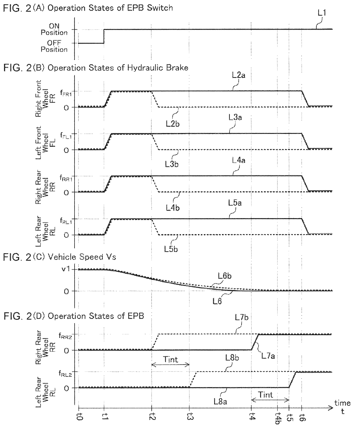
[0153](Case B) In a case where the ON operation of the EPB switch 60 is performed while the vehicle 10 is traveling / moving

[0154]It is assumed that the ON operation of the EPB switch 60 is performed while the vehicle 10 is traveling / moving afterwards. Namely, it is assumed that the present point in time is the time point t1 in the timing charts of FIGS. 2(A)-2(D). In the present assumption, it is also assumed that failure of the hydraulic brake 30 is not detected (namely, the hydraulic brake malfunction wheel is not detected) while the EPB stop process is in execution, and the OFF operation of the EPB switch 60 is not performed during a time period from the start of the EPB stop process to the stop of the vehicle 10.

[0155]In this case, the CPU makes a “Yes” determination in step 430 and proceeds to step 435 so as to set the value of the EPB stop process execution flag Xes to “1.” Subsequently, the CPU proceeds to step 440 so as to control the hydraulic brake 30 such that braking forc...

case c

[0165](Case C) In a case where the OFF operation of the EPB switch 60 is performed during execution of the EPB stop process

[0166]It is assumed that the OFF operation of the EPB switch 60 is performed during a time period from a time point at which the EPB stop process is started to a time point at which the vehicle 10 actually stops.

[0167]In this case, the CPU makes a “Yes” determination in step 525 and proceeds to 530. As a result, execution of the EPB stop process is aborted.

case d

[0168](Case D) In a case where the four wheels are detected as the hydraulic brake malfunction wheels during execution of the EPB stop process

[0169]It is assumed that all of the four wheels (namely, the left front wheel FL, the right front wheel FR, the right rear wheel RR, and the left rear wheel RL) are detected as the hydraulic brake malfunction wheels during the time period from a time point at which the EPB stop process is started to a time point at which the vehicle 10 actually stops.

[0170]In this case, since the specific condition is satisfied, the CPU makes a “Yes” determination in step 510 and proceeds to step 515 so as to set the value of the specific brake process execution flag Xoe to “1.” Subsequently, the CPU proceeds to step 520. In step 520, the CPU executes a “specific brake start process routine” represented by a flow shown chart in FIG. 6.

[0171]Specifically, the CPU starts the process from step 600 of FIG. 6 and proceeds to step 605 so as to determine whether or n...


PUM


Abstract

When an ON operation of an electric parking brake apparatus is performed when a vehicle is moving, a vehicle brake control apparatus executes an EPB stop process in order to stop the vehicle by braking force generated by a hydraulic brake apparatus. If a hydraulic brake malfunction wheel, at which the hydraulic brake apparatus cannot generate braking force properly, is detected during a time period from the beginning of the EPB stop process to the stop of said vehicle, the vehicle brake control apparatus makes the hydraulic brake apparatus stop generating braking force at wheels including the hydraulic brake malfunction wheel. Meanwhile, the vehicle brake control apparatus makes the electric parking brake apparatus start generating braking force at a rear wheel. Subsequently, the vehicle brake control apparatus makes the electric parking brake apparatus start generating braking force to the other rear wheel.

Description

BACKGROUND OF THE DISCLOSUREField of the Disclosure[0001]The present disclosure relates to a vehicle brake control apparatus which is applied to a vehicle which is equipped with a hydraulic brake apparatus and an electric parking brake apparatus.Description of the Related Art[0002]A vehicle which is equipped with a hydraulic brake apparatus and a parking brake apparatus is known. The hydraulic brake apparatus is disposed at each of four wheels which are provided in the vehicle, and generates braking force by driving a brake actuator using pressure of hydraulic oil (brake fluid). The hydraulic brake apparatus is mainly used for decelerating the vehicle. On the other hand, the parking brake apparatus is disposed at each of two rear wheels of the vehicle, and mainly used for maintaining the vehicle in a stop state.[0003]Further, an electric parking brake apparatus in which an electrical motor is utilized as an actuator of the parking brake apparatus is known. In substitution for a foot...

Claims


Application Information

Patent Timeline
Patent Type & Authority Patents(United States)
IPC IPC(8): B60T7/10F16H63/34B60T8/18B60T11/10F16H61/22
CPCB60T7/107B60T11/10F16H63/3491B60T8/1881B60T2270/40F16H2061/223B60T13/662B60T13/745B60T2260/08B60T2201/10B60T2270/402B60T8/326
Inventor SHIRAKAWA, SHINYA
Owner TOYOTA JIDOSHA KK
Why Eureka
Try Eureka