Web end

a technology of web end and closure, applied in the field of lanyards, can solve the problems of increased difficulty in the use of products, special tools, and greater complexity of products, and achieve the effect of convenient attachmen

Active Publication Date: 2006-03-21
ILLINOIS TOOL WORKS INC
View PDF15 Cites 43 Cited by
  • Summary
  • Abstract
  • Description
  • Claims
  • Application Information

AI Technical Summary

Benefits of technology

[0005]The present invention is directed to a lanyard that uses a single component to join the ends of the lanyard cord. The single component, referred to as a web end, folds together over the lanyard cord ends and snap fits onto the ends to secure the cord ends together. To secure the cord ends together, the web end uses numerous pins extending out from the web end that will engage with nume

Problems solved by technology

For example, known lanyards use multiple components to join the lanyard cord ends resulting in greater complexity of the product, use of special tools, and increased difficulty in the us

Method used


Image

  • Web end
  • Web end
  • Web end

Examples


Embodiment Construction

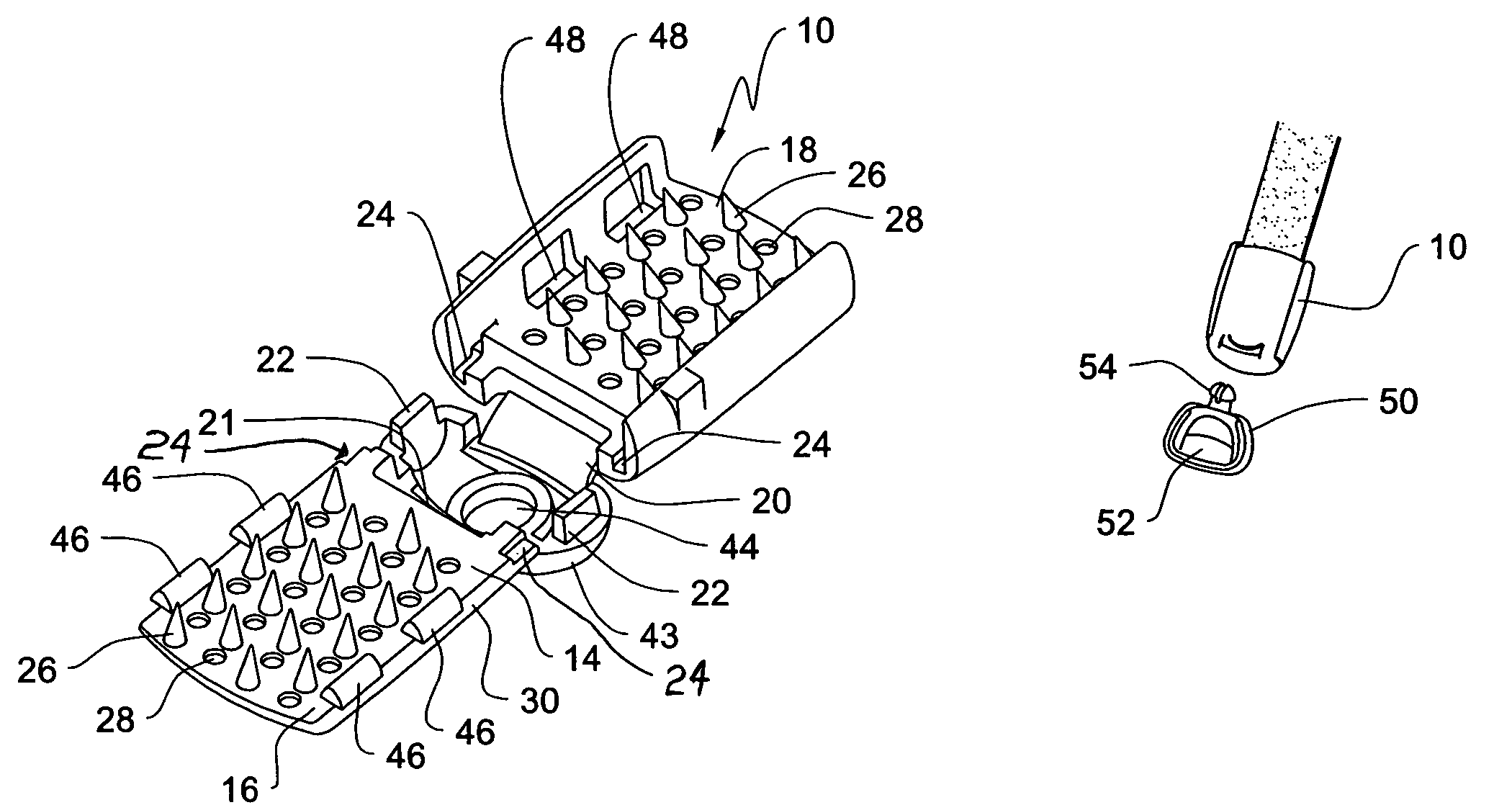
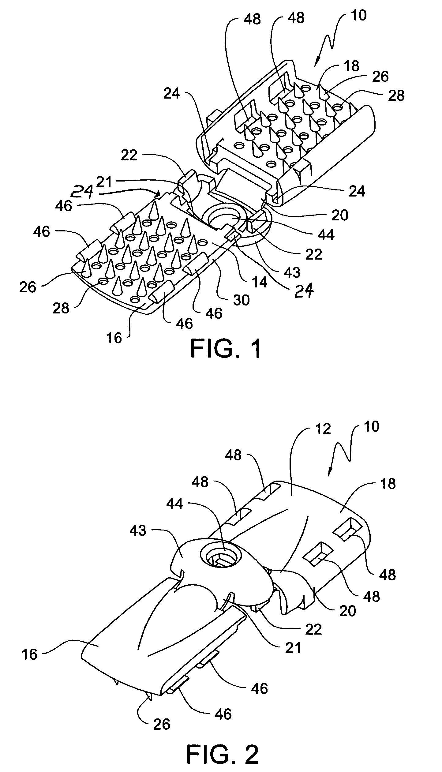
[0018]Referring to FIGS. 1 and 2, an exemplary embodiment of the invention is depicted as a one-piece web end 10. The web end 10, also referred to as a clip, is used to secure together the opposing ends of a lanyard cord. Once secured together, the lanyard forms a loop that may be placed over a person's head and around the neck. The web end 10 may also receive an attachment member, discussed below, that can be used to mount or connect an identification badge, tag or other object to the lanyard.

[0019]As illustrated in FIGS. 1 and 2, the web end or clip 10 is depicted in an open, unattached and unsnapped position. In this position, the web end 10 defines an outer surface wall 12, an inner surface wall 14, and opposing ends 16, 18. Located between and connecting the opposing ends 16, 18 of the web end 10 are hinges 20, 21 that permit the opposing ends 16, 18 to fold together. It should be understood that the invention may use fewer hinges to permit the folding together of the ends 16, ...


PUM


Abstract

A one-piece clip or web end to join the cord ends of a lanyard is disclosed. The clip folds together and snap fits onto the cord ends to secure the ends together. The clip includes numerous pins extending outwardly from the clip body that mate with numerous pin pockets formed in the clip body to secure the cord ends together. The clip further includes mating locking tabs, and stabilizing ribs and recesses to facilitate the easy snap fit of the clip onto the cord ends of the lanyard without the use of special tools.

Description

CROSS REFERENCE TO RELATED APPLICATION[0001]This Non-Provisional Application claims benefit to U.S. Provisional Application Ser. No. 60 / 440,213 filed Jan. 15, 2003.FIELD OF THE INVENTION[0002]The present invention relates generally to lanyards and more particularly to closures for lanyards that snap onto lanyard ends and are used to hold security or trade show identification badges or the like.BACKGROUND OF THE INVENTION[0003]It is known that lanyards are used to suspend identification or security badges, keys, cell phones, or other objects around a person's neck. Conventional lanyards include the use of a small cord or rope that is joined together at the cord ends to form a loop that fits over a person's head and around the neck. There are several known techniques to join the cord ends of the lanyard to form a loop. These techniques include tieing or gluing the cord ends together, or using multiple fastener components that must be attached onto the cord ends and then secured togeth...

Claims


Application Information

Patent Timeline
IPC IPC(8): F16L11/00A44B99/00
CPCA44B99/00Y10T24/47Y10T24/3987Y10T24/1374Y10T24/3916Y10T24/39
Inventor TRACY, RICHARD J.
Owner ILLINOIS TOOL WORKS INC
Why Eureka
Try Eureka