
Testing device for testing a drainage system for leaks

a drainage system and leak detection technology, applied in the direction of measurement devices, measuring/machine measurement, instruments, etc., can solve the problems of prior art testing devices not meeting the need for enabling plumbers, unnecessary difficulty in installing and removing prior art testing devices, etc., to achieve the effect of improving work efficiency, safer and cleaner

Inactive Publication Date: 2006-03-21
HERBERS CHARLES R
View PDF32 Cites 12 Cited by
  • Summary
  • Abstract
  • Description
  • Claims
  • Application Information

AI Technical Summary

Benefits of technology

[0020]It is another object of the present invention to provide a testing device which provides the tester with full control at test point.
[0033]A closure plug assembly is disclosed and comprises a bushing plug defining an annular top having a peripheral edge which extends outward peripherally so as to form an annular recess. The bushing plug is lined with male threads peripheral to facilitate threaded coupling to inlet. A rubber O-ring gasket is disposed about an external circumferential surface of bushing plug below annular recess. The rubber O-ring gasket facilitates sealable engagement by bushing plug with inlet.

Problems solved by technology

The prior art devices of the class under consideration are characterized by several deficiencies, chiefly among these being the requirement of pumps, transportation of hosing up and down floors, interruption of the test when fixing a leak on an upper level floor, wet flooring from test ball-blow out at testing location, and unnecessary difficulty in installing and removing prior art test devices.
Additionally, the prior art testing devices have failed to address the need for enabling a plumber to determine the particular elevation or floor at which water level is being measured during a testing sequence.

Method used


Image

  • Testing device for testing a drainage system for leaks
  • Testing device for testing a drainage system for leaks
  • Testing device for testing a drainage system for leaks

Examples


Embodiment Construction

1. Detailed Description of the Figures

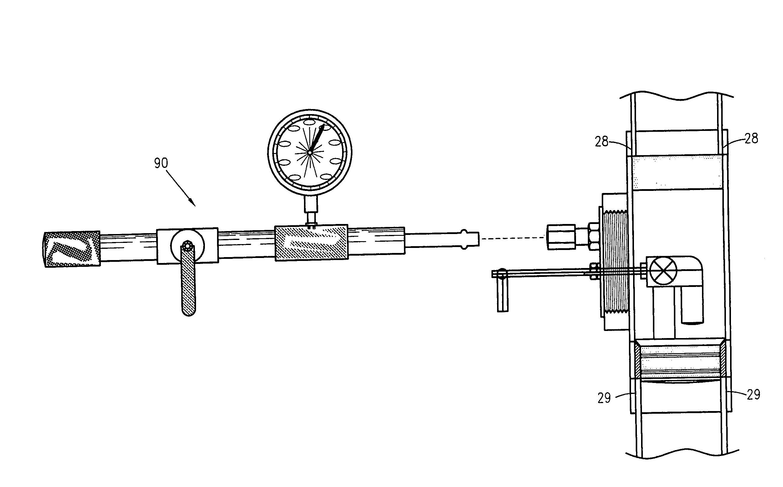
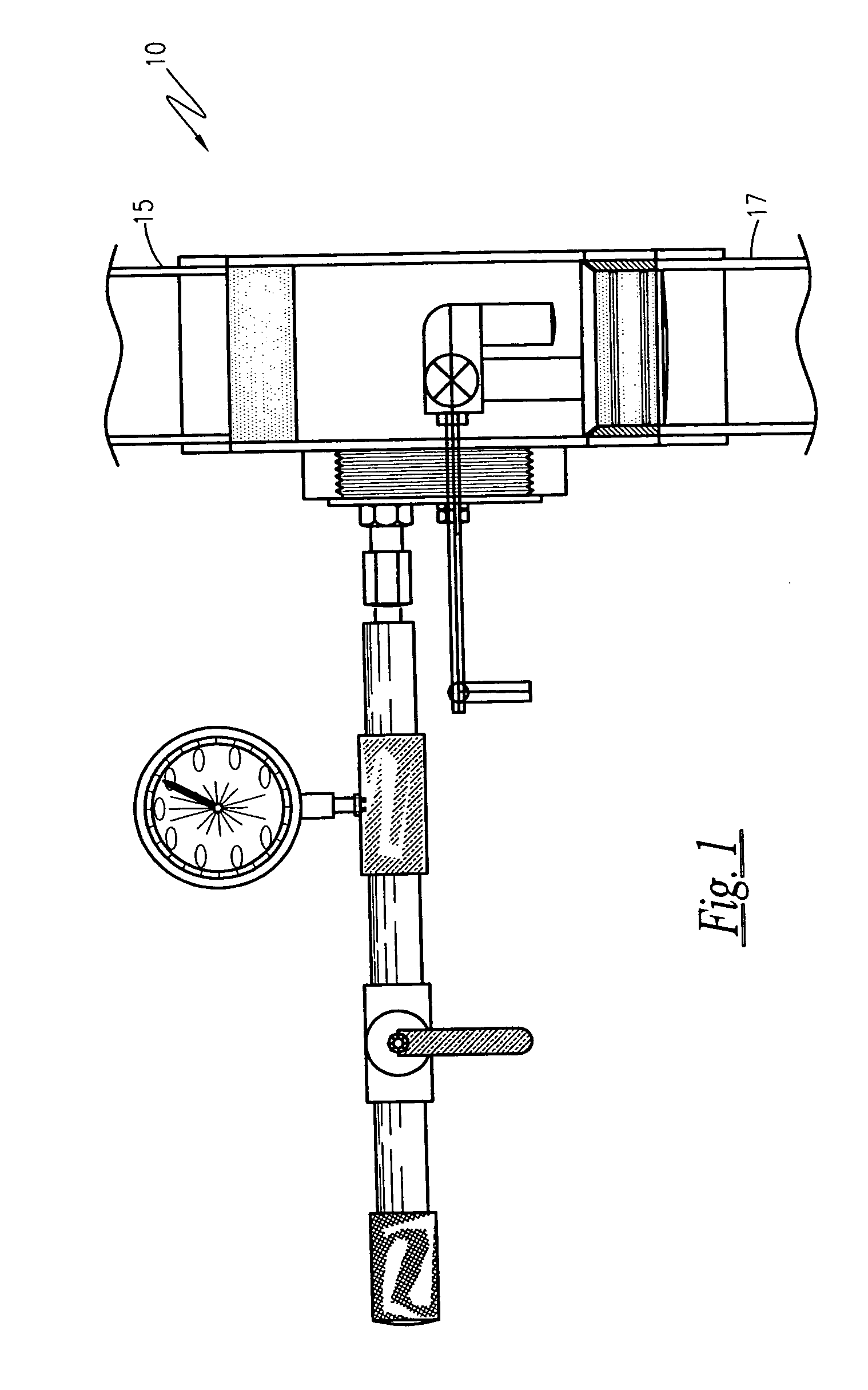
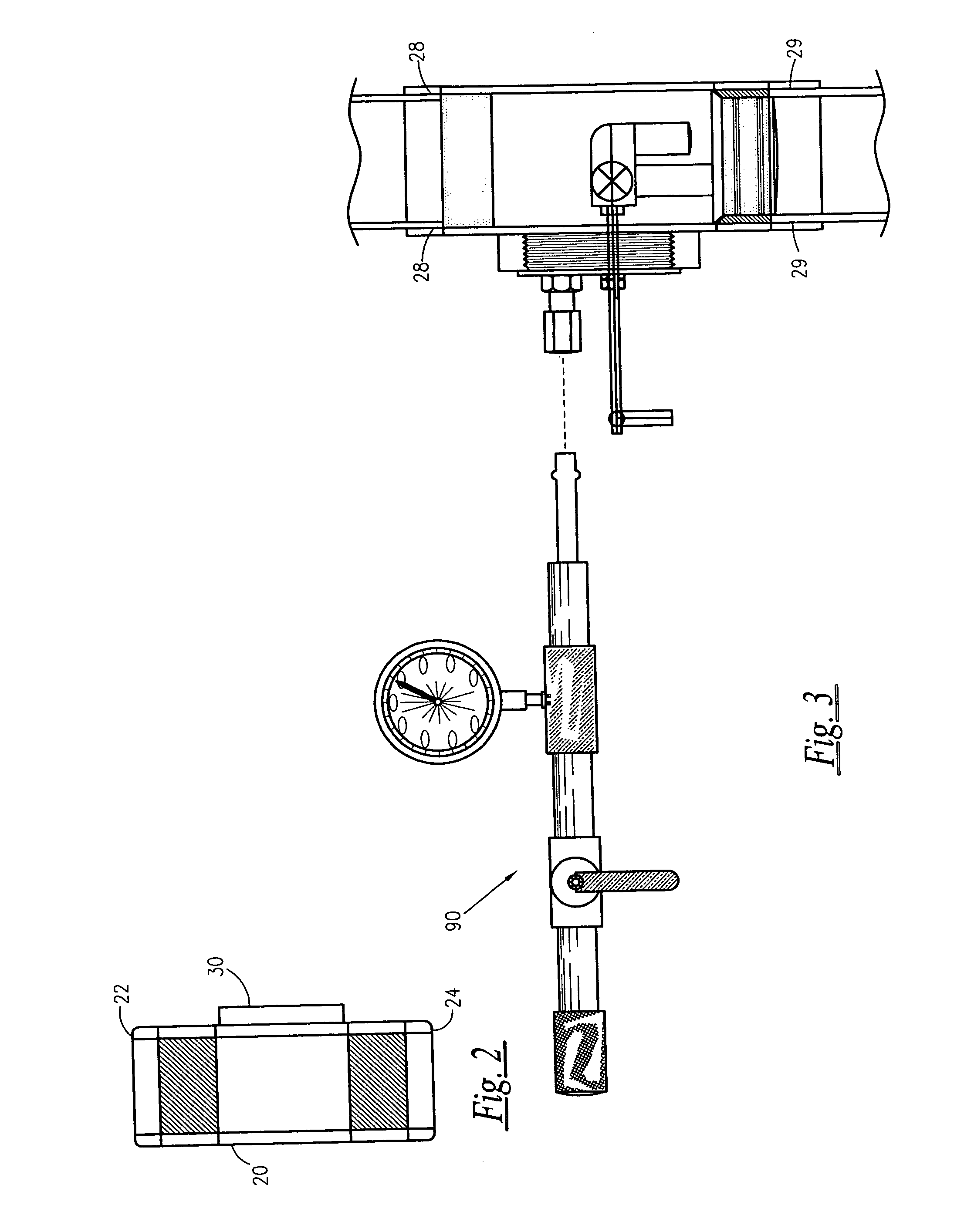
[0049]Referring now to FIGS. 1–6, an improved testing device for testing a drainage system for leaks 10 is shown, hereinafter testing device 10, according to the present invention, adapted for testing a drainage or plumbing system for leaks in multi-story buildings. The testing device 10 is comprised of an elongated, tubular member 20 having an upper end 22 opposing a lower end 24. The tubular member 20 is disposed in fluid tight series communication between a drainage system 15 and drain 17. The upper end and lower end 24 of tubular member 20 define sockets 28 and 29, respectively for receiving an end of the drainage system 15 and an end of the drain 17, respectively. Once disposed in a desired location, the tubular member 20 is adapted to remain in position as a clean out. The tubular member 20 defines an annular ledge 26 disposed between the upper end 22 and lower end 24 of tubular member 20. The annular ledge 26 is angularly oriented or incl...


PUM


Abstract

An improved testing device for testing a drainage or plumbing system for vertical piping is provided which allows the tester to determine which particular floor is being currently checked for leaks at any time during the test. The testing device includes a tee disposed in fluid tight series communication between a drainage system and drain. A controller means is included which utilizes a ball valve to prevent water spillage during removal of the testing device when testing the drainage system for leaks. A ball valve actuator facilitates actuation of the ball valve. A closure plug assembly is provided which includes multiple ports adapted to accommodate a valve stem of the controller means and a fillgauge apparatus. A fluid elevation gauge provides tester with a visual readout of water elevational levels. A lightweight container is provided to store the testing device to facilitate transportability.

Description

RELATED APPLICATIONS[0001]There are no previously filed, nor currently any co-pending applications, anywhere in the world.BACKGROUND OF THE INVENTION[0002]1. Field of the Invention[0003]The present invention relates generally to devices for testing leaks in drainage systems and, more particularly, to an improved testing device for testing a drainage or plumbing system for vertical piping.[0004]2. Description of the Related Art[0005]During the construction of single and multi-story buildings, such as office complexes or multi-story residential condominium-like structures, drainage stacks are interconnected in order that water and sewage flows from various floors of the building down standpipe drains to drainage systems. Before completion of the building, plumbing codes require that a pressure test be run on installed plumbing lines to inspect for leaks.[0006]The prior art devices of the class under consideration are characterized by several deficiencies, chiefly among these being the...

Claims


Application Information

Patent Timeline
Patent Type & Authority Patents(United States)
IPC IPC(8): G01M3/08
CPCG01M3/2815
Inventor HERBERS, CHARLES R.
Owner HERBERS CHARLES R
Learn More