
Variable tooth saw blade

a technology of tooth saw blades and variable blades, which is applied in the field of variable blades, can solve the problems of excessive noise and less than desirable cuts

Inactive Publication Date: 2006-03-21
BLACK & DECKER INC
View PDF13 Cites 31 Cited by
  • Summary
  • Abstract
  • Description
  • Claims
  • Application Information

AI Technical Summary

Benefits of technology

The present invention provides a saw blade with a flat circular disc and a plurality of teeth that have cutting edges. The blade has three groups of cutting edges with different widths. The first group has a width of approximately sixty degrees, the second group has a width of approximately forty degrees, and the third group has a width of approximately thirty degrees. The blade also has four spaces between the groups, each with a different width. The technical effect of this invention is to provide a saw blade with improved cutting performance and efficiency.

Problems solved by technology

The high speed at which blades rotate often causes high levels of harmonic vibration leading to excessive noise, undesirable saw or saw blade vibration, and if the vibration is significant, a less than desirable cut.

Method used


Image

  • Variable tooth saw blade
  • Variable tooth saw blade
  • Variable tooth saw blade

Examples


first embodiment

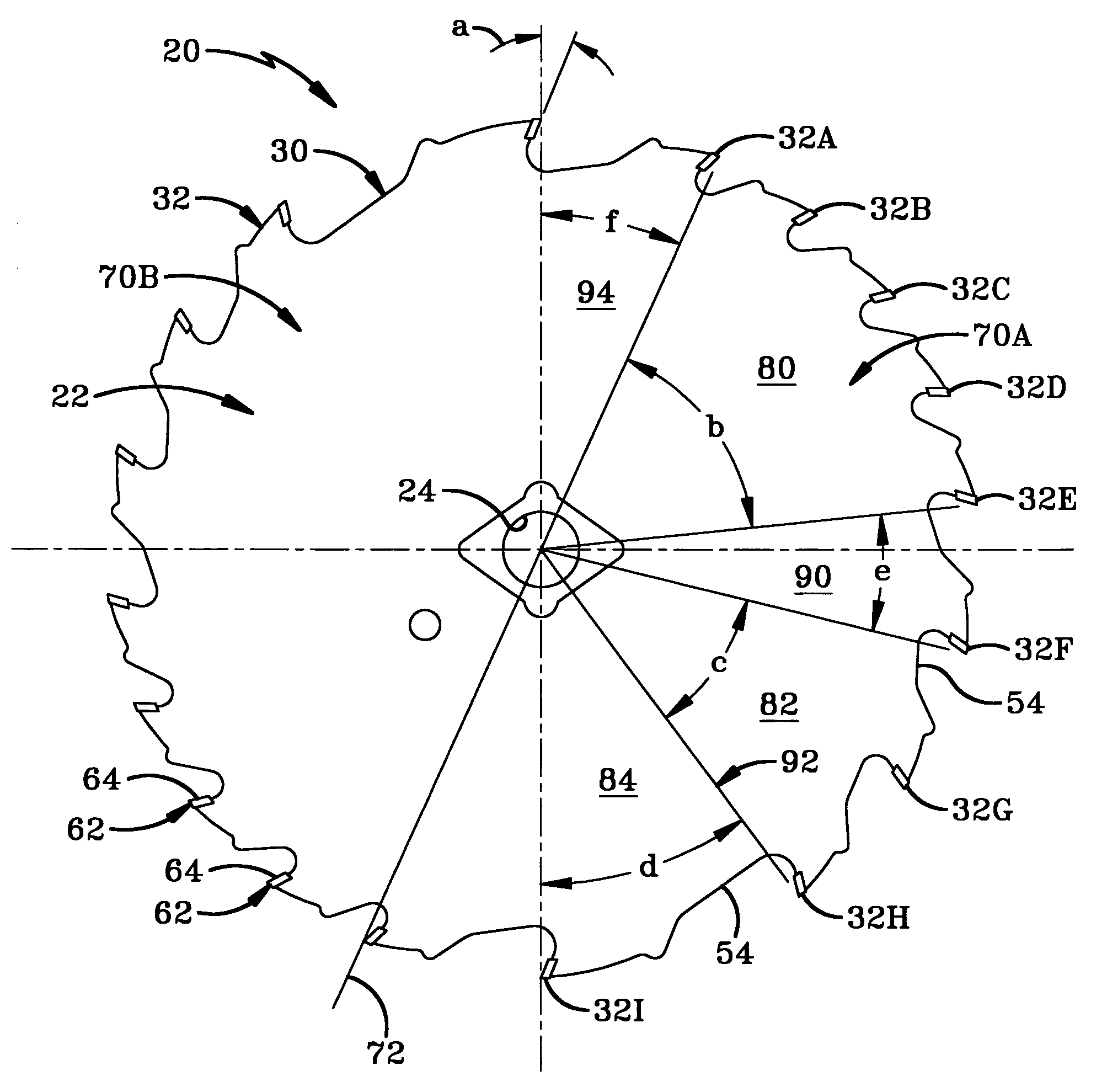
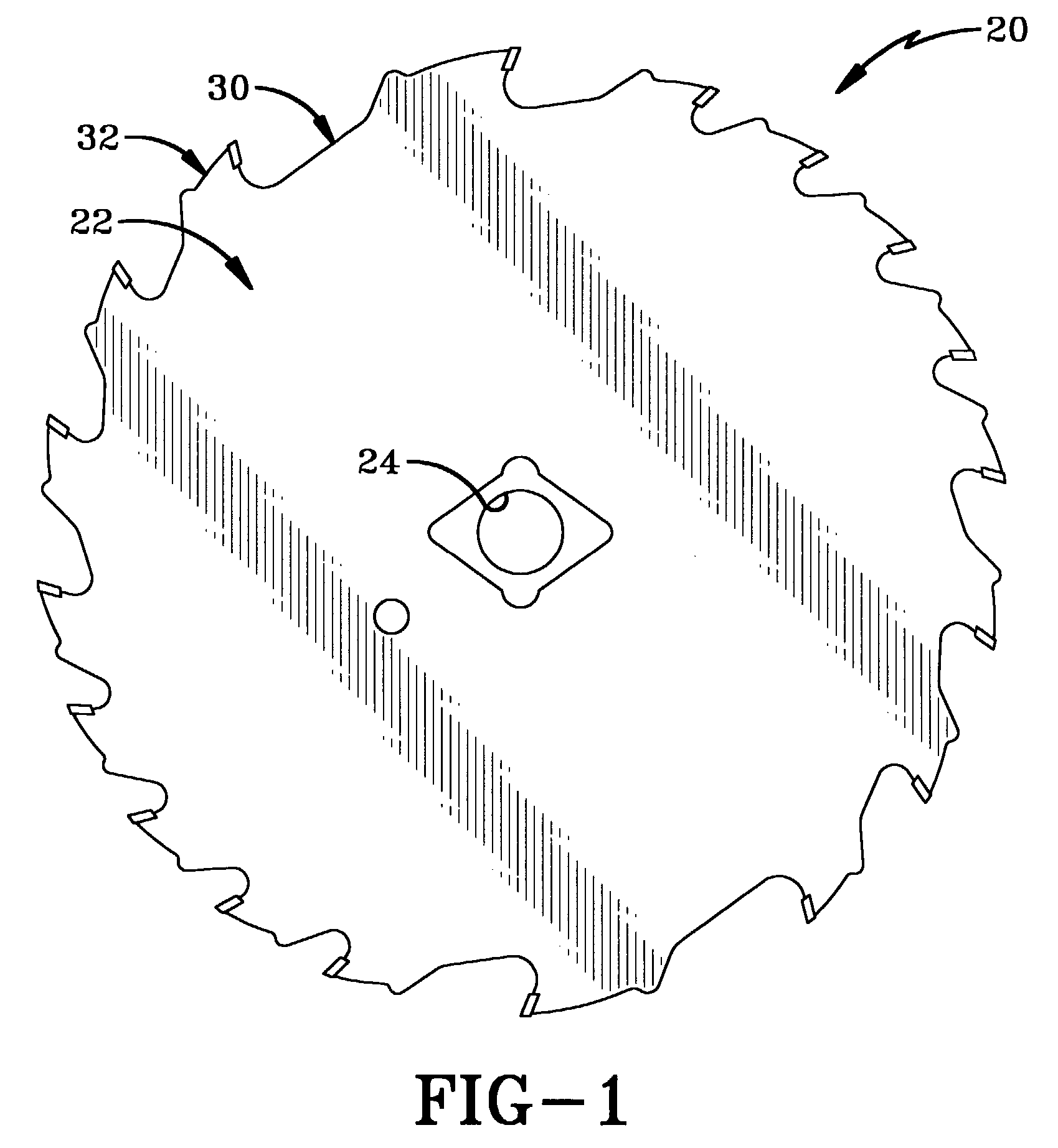
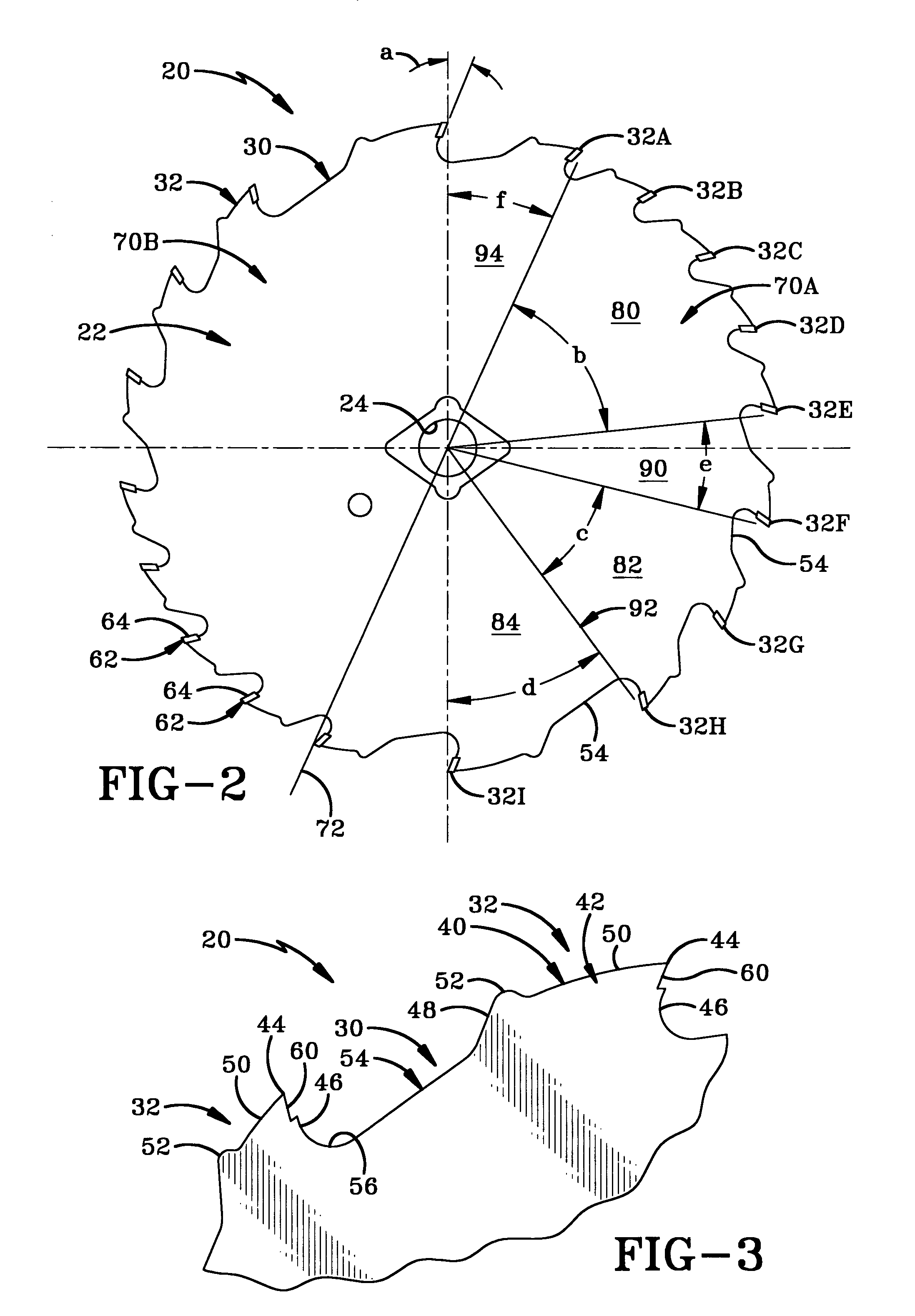
[0020]The first embodiment is saw blade 20 embodied as a standard seven and one quarter inch diameter saw blade although it may be of any other diameter used or contemplated by those of skill in the art. The saw blade whether embodied as blade 20 or 120 is a flat, circular disc 22, made of steel or other like metals, with a center arbor hole 24 as is well known in the art. The disc 22 includes a peripheral edge 30 with a plurality of circumferentially-spaced teeth projecting radially outwardly therefrom for cutting and generally referred to as 32. Each tooth 32 has a cutting edge 44 and is more fully described below.

[0021]In accordance with one of the features of the invention, the blade is divided into an even number of groups or sections, and in more detail the blade 20 in the first embodiment is divided into two halves of six sections while the blade 120 in the second embodiment is divided into two halves of eight sections. Each section along the peripheral edge has a matching or...

second embodiment

[0032]In more detail as to the blade referred to as 120, teeth 32 are arranged in a unique thirty-six tooth design that is divided into two copy exact sections, namely a first side 170A and a second side 170B by axis 172. Since the blade as shown in FIGS. 4–5 has a right and left copy exact side (sides 170A and 170B respectively), only the right side will be described below (except where necessary to refer to the left side). The first side 170A includes eighteen teeth, namely teeth 132A, 132B, 132C, 132D, 132E, 132F, 132G, 132H, 132I, 132J, 132K, 132L, 132M, 132N, 132O, 132P, 132Q, and 132R.

[0033]As with the first embodiment and in accordance with one of the features of the invention, the eighteen teeth 132A, 132B, 132C, 132D, 132E, 132F, 132G, 132H, 132I, 132J, 132K, 132L, 132M, 132N, 132O, 132P, 132Q, and 132R of each side 170A and 170B are not all identical in size and spacing. Specifically in the embodiment shown, first side 170A is divided into four sections 180, 182, 184 and 1...


PUM

PropertyMeasurementUnit
hook angleaaaaaaaaaa

Abstract

An apparatus for cutting materials and more specifically an improved saw blade includes a plurality of variable teeth thereon. The variable tooth saw blade cuts faster and smoother while reducing harmonic vibrations. Specifically, the teeth on the saw blade are grouped into sections with differing circumferential widths and differing spacing between the sections.

Description

BACKGROUND OF THE INVENTION[0001]1. Technical Field[0002]This invention relates to rotary saw blades, and more particularly circular saw blades for use on circular saws or the like. Specifically, the invention is directed to a variable tooth saw blade that cuts faster and smoother while reducing harmonic vibrations.[0003]2. Background Information[0004]Circular saw blades are readily available for use in cutting wood and other materials using a portable, hand-held circular saw, or a fixed table or radial saws, or other like saws. The saw blades are formed of flat, circular discs made of steel or other like metals. As is well known in the art, circular saw blades include a peripheral edge from which a plurality of circumferentially-spaced teeth project radially outwardly for cutting.[0005]Users continually desire to purchase blades that allow for faster cutting without negative effects such as “burning” of the blade, dulling of the teeth, or jamming of the saw. The ability of the teet...

Claims


Application Information

Patent Timeline
Patent Type & Authority Patents(United States)
IPC IPC(8): B27B33/08B23D61/02
CPCB23D61/021Y02P70/10Y10T83/9319Y10T83/935Y10T83/9358Y10T83/9367Y10T83/9403
Inventor LOWDER, JEREMY A.VILAGI, SCOTT A.
Owner BLACK & DECKER INC
Learn More