

Method for determining tribological properties of a sample surface using a scanning microscope (sem) and associated scanning microscope
a scanning microscope and sample surface technology, applied in the direction of mechanical measurement arrangements, mechanical roughness/irregularity measurements, instruments, etc., can solve the problems of ultrasonically induced normal vibrations of the sample surface transmitted, and local resolution has proven unsatisfactory, and achieve fine resolution of the tribological method of analysis. , the effect of high sensitiv
- Summary
- Abstract
- Description
- Claims
- Application Information
AI Technical Summary
Benefits of technology
Problems solved by technology
Method used
Image

Examples
Embodiment Construction
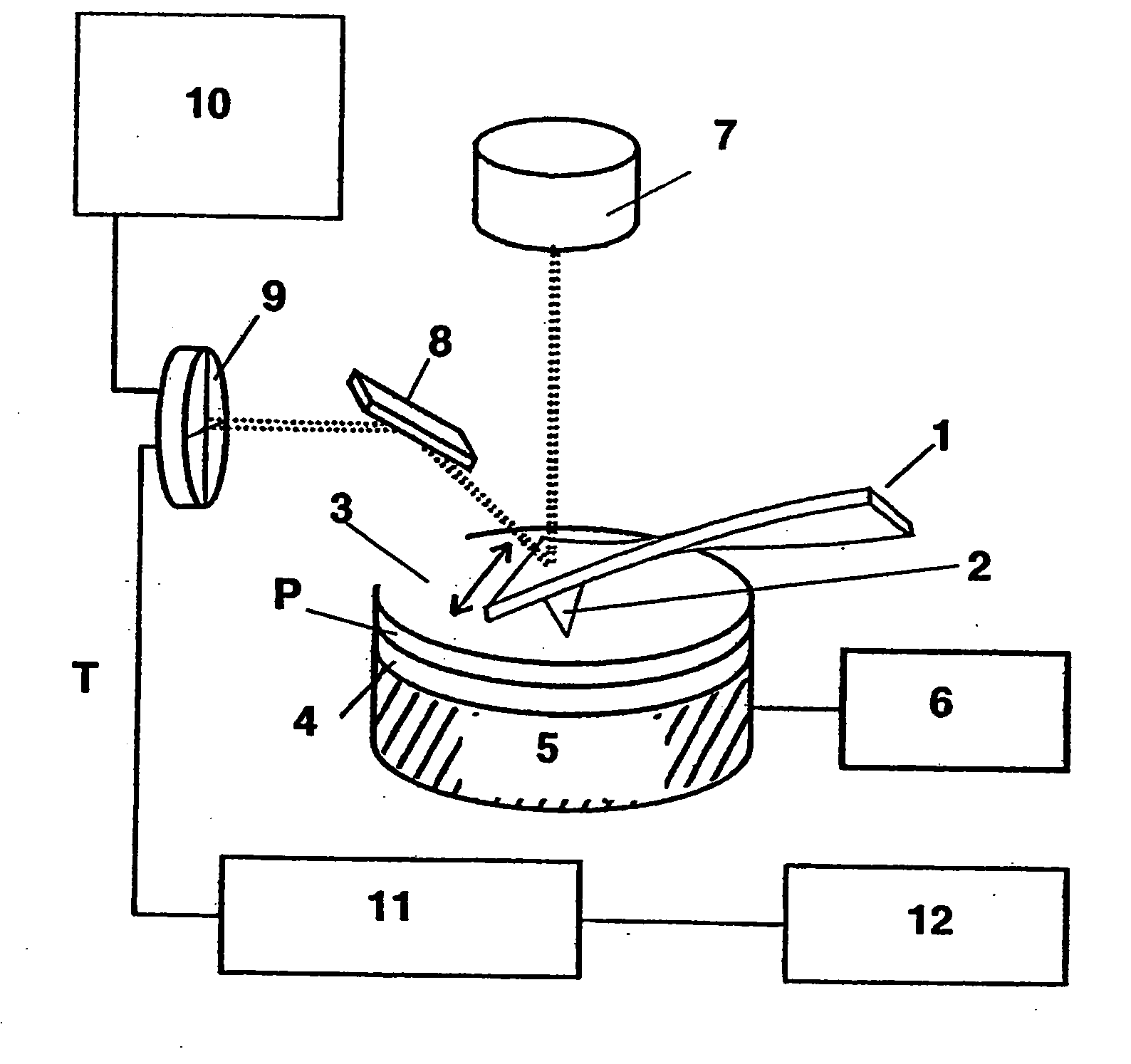
[0012] The object of the present invention is to further develop a method for examining a surface sample using an atomic force scanning microscope of the aforedescribed manner, in which vibrations are induced in the surface sample, the vibrations being directed lateral to the sample surface and, moreover, being oriented perpendicular to the longitudinal extension of the cantilever, in such a manner that it is possible to obtain qualitative and quantitative information about the frictional properties of the sample surface. In particular, the object is to permit high locally resolved determination of the tribological, i.e. frictional properties of the sample surface, by means of superimposing a topography measurement, permitting in this manner finely as possibly resolved sample surface mapping with a local resolution of less than 100 nm, preferably less than 10 nm.
[0013] The solution to the object of the present invention is set forth in claim 1. Advantageous features that further de...
PUM
| Property | Measurement | Unit |
|---|---|---|
| length | aaaaa | aaaaa |
| length | aaaaa | aaaaa |
| length | aaaaa | aaaaa |
Abstract
Description
Claims
Application Information