Method for determining tribological properties of a sample surface using a scanning microscope (sem) and associated scanning microscope

a scanning microscope and sample surface technology, applied in the direction of mechanical measurement arrangements, mechanical roughness/irregularity measurements, instruments, etc., can solve the problems of ultrasonically induced normal vibrations of the sample surface transmitted, and the local resolution has proven unsatisfactory, so as to achieve high local resolution determination

Inactive Publication Date: 2008-04-22
FRAUNHOFER GESELLSCHAFT ZUR FOERDERUNG DER ANGEWANDTEN FORSCHUNG EV
View PDF6 Cites 14 Cited by
  • Summary
  • Abstract
  • Description
  • Claims
  • Application Information

AI Technical Summary

Benefits of technology

[0014]The present invention is a method for examining a surface sample using an atomic force scanning microscope of the aforedescribed manner, in which vibrations are induced in the surface sample, the vibrations being directed lateral to the sample surface and, moreover, being oriented perpendicular to the longitudinal extension of the cantilever, in such a manner that it is possible to obtain qualitative and quantitative information about the frictional properties of the sample surface. In particular, method permits high locally resolved determination of the tribological, that is frictional properties of the sample surface, by means of superimposing a topography measurement, permitting in this manner finely as possibly resolved sample surface mapping with a local resolution of less than 100 nm, preferably less than 10 nm.
[0017]With the aid of the method of the invention, tribological properties, thus for example, the frictional forces or the frictional coefficients acting between the measuring tip and the sample surface, are detected at the sample surface with a local resolution of up to 1 nm. Compared to prior art methods, which at best permit local resolution of approximately 100 nm, the method of the invention is a highly sensitive and most finely suited to a resolving tribological method of analysis. In addition to determining tribological properties at a sample surface, the method of the invention, of course, also permits determination of the topography by adjusting a constant vertical load which the measuring tip of the cantilever lies on the to-be-examined sample surface. With the aid of a means for detecting, low-frequency excursions of the measuring tip are detected via the reflection of light at the cantilever and correspondingly evaluated. The detection signal obtained with the means for detecting representing the low-frequency topography-based excursion of the measuring tip serves, on the one hand, to determine the topography and, on the other hand, as a regulation value, with which the distance between the measuring tip and the sample surface, and the vertical load with which the measuring tip lies on the sample surface is held constant and temporally averaged. In this manner, the method of the invention permits rendering in successive scanning of the surface an accurate microscopic topographic image of the sample surface in a scale of up to 1 nm, the image being able at the same time to provide tribological information about the sample surface.

Problems solved by technology

The problem with this measuring situation that needs to be resolved lies in the decoupling due to the measurement of the superimposed excursions of the cantilever, which result, on the one hand, from the topography measurement due to which the vertical load with which the measuring tip lies on the sample surface remains, as constant as possible and, on the other hand, which cause the ultrasonically induced normal vibrations of the sample surface transmitted to the cantilever via the measuring tip.
However, with this measuring method, local resolution has proven unsatisfactory.
Moreover, the measuring quality achievable with this method permits obtaining only qualitative information about the frictional properties of the sample surface.

Method used


Image

  • Method for determining tribological properties of a sample surface using a scanning microscope (sem) and associated scanning microscope
  • Method for determining tribological properties of a sample surface using a scanning microscope (sem) and associated scanning microscope

Examples


Embodiment Construction

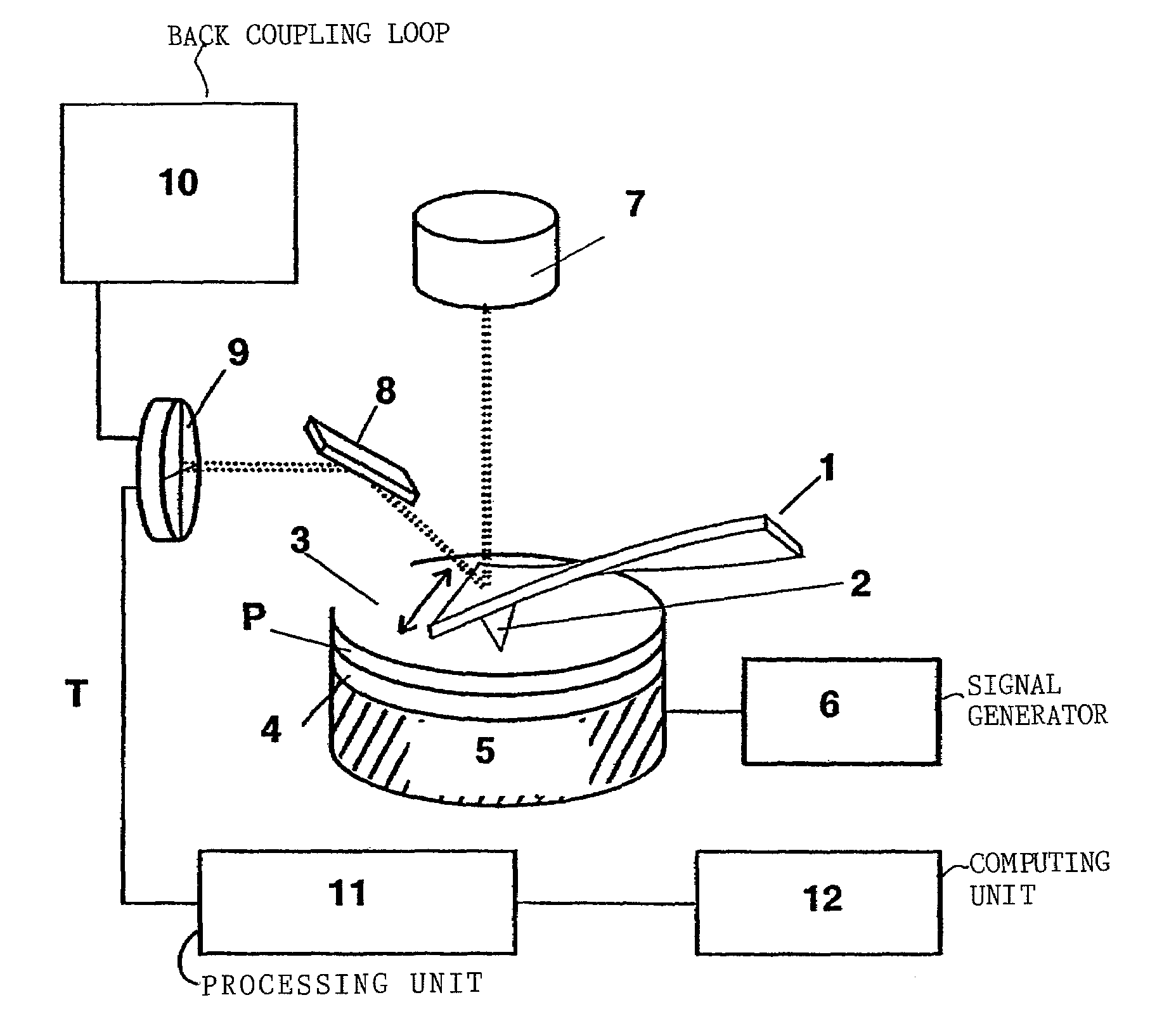
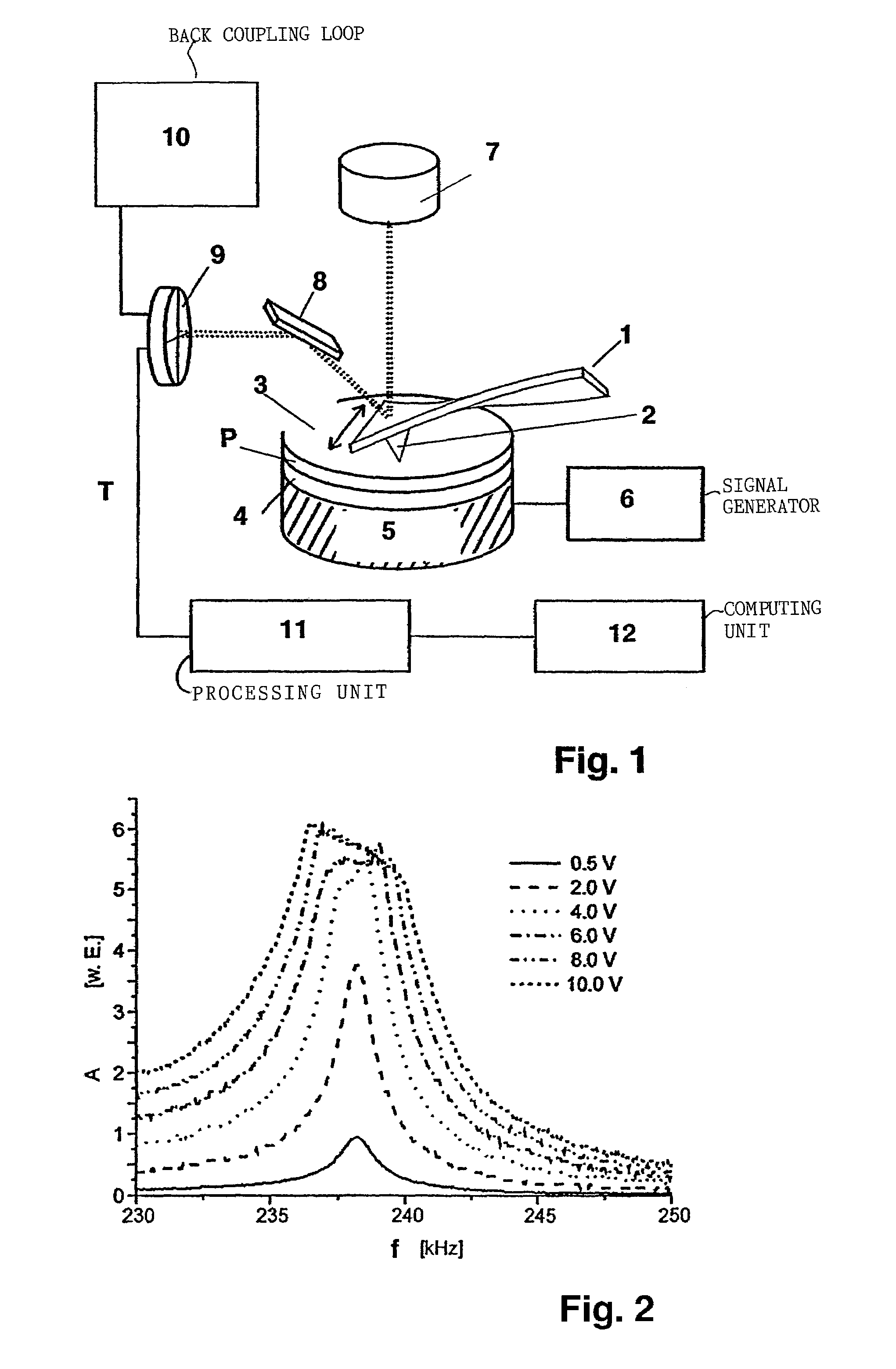
[0032]FIG. 1 shows an atomic force scanning microscope for conducting the method of the invention for examining a sample surface, in particular for determining tribological properties on the sample surface. The microscope depicted in FIG. 1 is provided with a cantilever 1, whose measuring tip 2 lies on the sample surface 3 of a sample P. Sample P is in contact with an ultrasonic transducer 5 via a pre-run track or pre-run layer 4. The ultrasonic transducer 5 is set into oscillations by a corresponding signal generator 6. The pre-run layer 4 is, for example, connected on both sides to the sample P and the ultrasonic transducer via a honeycomb layer as an acoustic coupling layer.

[0033]An optical sensor unit comprising a laser diode 7, a deflection mirror 8 and a photodiode unit 9, is provided for measuring the vibrations conveyed into the cantilever 1 via the measuring tip 2. The photodiode unit 9 serves, on the one hand, to detect the topographically based, low-frequency excursions o...


PUM


Abstract

A method for examining a surface of a sample is described using an atomic force scanning microscope (AFM) comprising a cantilever with a longitudinal extension along which a measuring tip is disposed, which is selectively arranged relative to the sample surface by a means for driving and whose spatial position is detected using a sensor unit. Vibration excitation is conducted at excitation amplitudes which produce inside the cantilever torsional amplitudes with maximum values which form a largely (substantively) constant plateau value despite increasing excitation amplitudes and the resonance spectra, in a range of maximum values of the torsional amplitudes, a widening of the resonance spectrum which is determinable by a plateau width. The resonance spectra, preferably the plateau value, the plateau width and / or the gradient of the respective resonance spectra are used for examining the sample.

Description

BACKGROUND OF THE INVENTION[0001]1. Field of the Invention[0002]The present invention relates to a method for examining a sample surface using an atomic force scanning microscope comprising a cantilever with a longitudinal extension, along which the measuring tip is arranged precisely relative to a sample surface by means of a means for driving, the spatial position of the measuring tip being determined by a sensor unit. The microscope is further provided with at least one ultrasound generator with which vibration excitation is initiated at a given excitation frequency between the sample surface and the cantilever. The measuring tip of the cantilever is brought into contact with the sample surface in such a manner that the oscillations imparted to the measuring tip are oriented lateral to the sample surface and perpendicular to the length of the cantilever. The torsional vibrations induced in the cantilever are detected and analyzed by means of an evaluation unit.[0003]2. Descriptio...

Claims


Application Information

Patent Timeline
Patent Type & Authority Patents(United States)
IPC IPC(8): G01B5/28G01N13/16G01B21/30G01H3/00G01N29/22G01N29/34G01Q60/26G01Q60/28
CPCB82Y35/00G01H3/00G01N29/22G01Q60/28G01Q60/26G01N29/346G01N2291/02827G01N2291/101
Inventor REINSTADTLER, MICHAELRABE, UTEARNOLD, WALTER
Owner FRAUNHOFER GESELLSCHAFT ZUR FOERDERUNG DER ANGEWANDTEN FORSCHUNG EV
Why Eureka
Try Eureka