Dry-sump, four-stroke engine lubrication device

a lubrication device and dry-sump technology, which is applied in the direction of pressure lubrication, closed-circuit pressure lubricating system, lubrication elements, etc., can solve the problems of blown lubricant oil near the crank web, inability to prevent the flow of lubricant oil into the clutch chamber, and inability to prevent the lubricant oil from being blown away from the periphery of the crank web, etc., to achieve large pressure differential larg

Active Publication Date: 2006-03-21
YAMAHA MOTOR CO LTD
View PDF2 Cites 6 Cited by
  • Summary
  • Abstract
  • Description
  • Claims
  • Application Information

AI Technical Summary

Benefits of technology

[0016]In this type of structure, the through holes open in the stroke where the piston moves from the top dead center position toward the bottom dead center position so gas within the crank chamber is pressed along with the lubricant oil into another chamber. The pressure fluctuation within the crank chamber is therefore alleviated and pumping loss is reduced.
[0017]In the stroke where the piston moves from the bottom dead center position to the top dead center position, the crank web blocks the through holes. The crank web and the through holes therefore function as a check valve. The negative pressure generated in the crank chamber therefore cannot escape to the separate chamber by way of the through holes, so that a large pressure differential occurs between the crank chamber and the separate chamber. Lubricant oil that flowed into the separate chamber can therefore be efficiently suctioned from the return holes in the crank chamber, and the lubricant oil can efficiently return to the crank chamber.

Problems solved by technology

The increase in pressure inside the crank chamber while the piston falls downward from the top dead center to the bottom dead center is especially large in large displacement single-cylinder and V-type two-cylinder engines so that the lubricant oil in the vicinity of the crank web is blown away due to the air pressure that accompanies the fall of the piston.
However when these through holes in the sidewall are open, the lubricant oil is blown away from the periphery of the crank web, and cannot be prevented from flowing into the clutch chamber from the through holes.
The pressure differential between the crank chamber and the clutch chamber therefore can be relieved, and this makes it difficult for lubricant oil to return to the crank chamber from the clutch chamber.
This situation leads to problems since the oil tank has to be enlarged, the level of lubricant oil inside the clutch chamber rises, and the lubricant oil agitation resistance increases due to the wet-type clutch.
This requires increasing the number of engine parts, requires drastic changes to the crankcase design to be used for already built engines, and therefore leads to higher costs.
A further problem with the above engine of the prior art is that it also requires providing a space for installing the reed valve at the bottom of the crankcase.
The overall height of the engine therefore becomes larger and the merits of the dry-sump, four-stroke engine are lost.
This valve body might collapse and be destroyed if it is repeatedly subjected to pressure from the crank chamber.
In that case, the valve body might make contact with the crank web and valve body debris might fly into the crank chamber.
Therefore this debris might possibly cause damage to the crankshaft bearing or the section coupling the crank pin and crankshaft.

Method used


Image

  • Dry-sump, four-stroke engine lubrication device
  • Dry-sump, four-stroke engine lubrication device
  • Dry-sump, four-stroke engine lubrication device

Examples


Embodiment Construction

[0034]The first embodiment of the present invention is described next referring to FIG. 1 through FIG. 11.

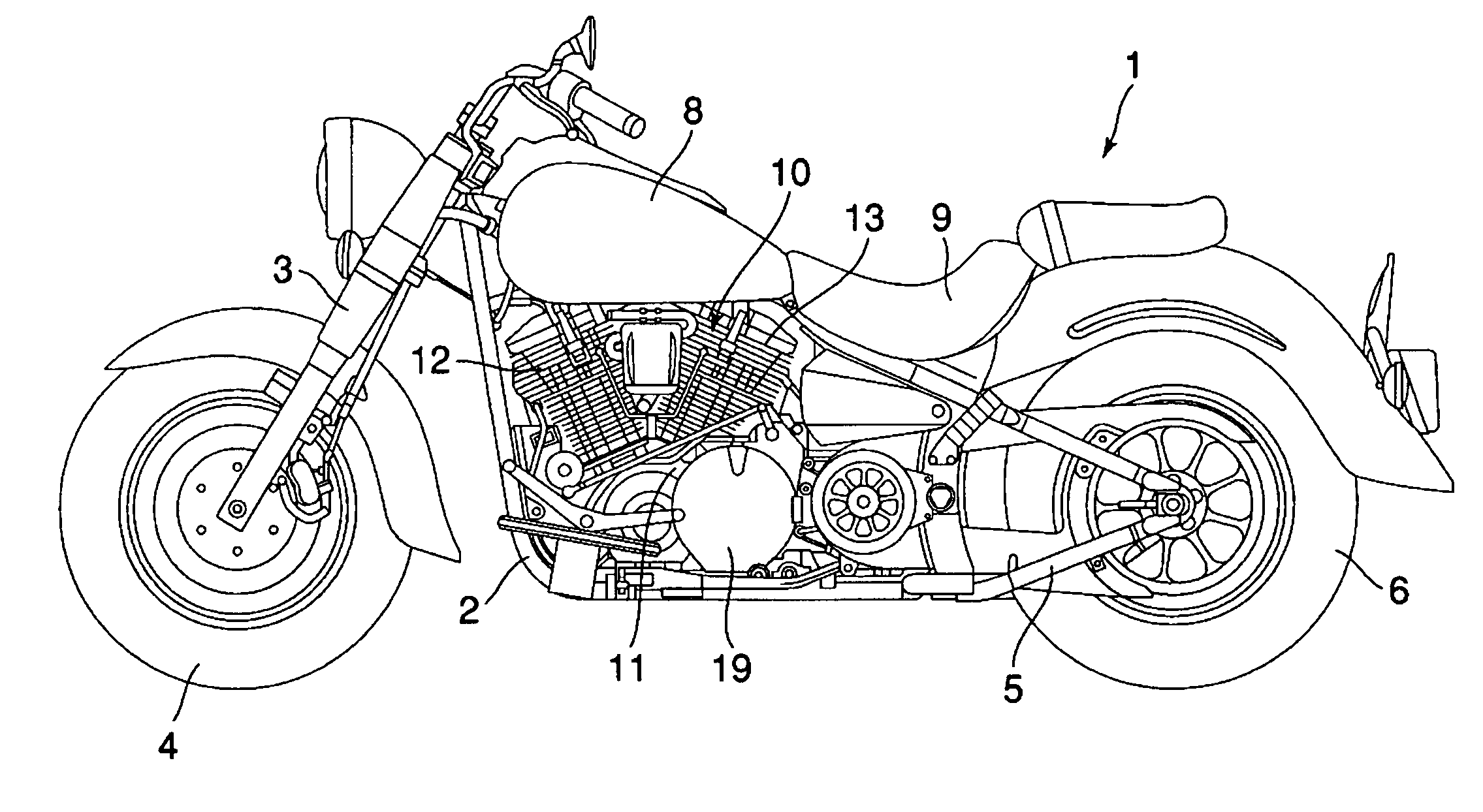
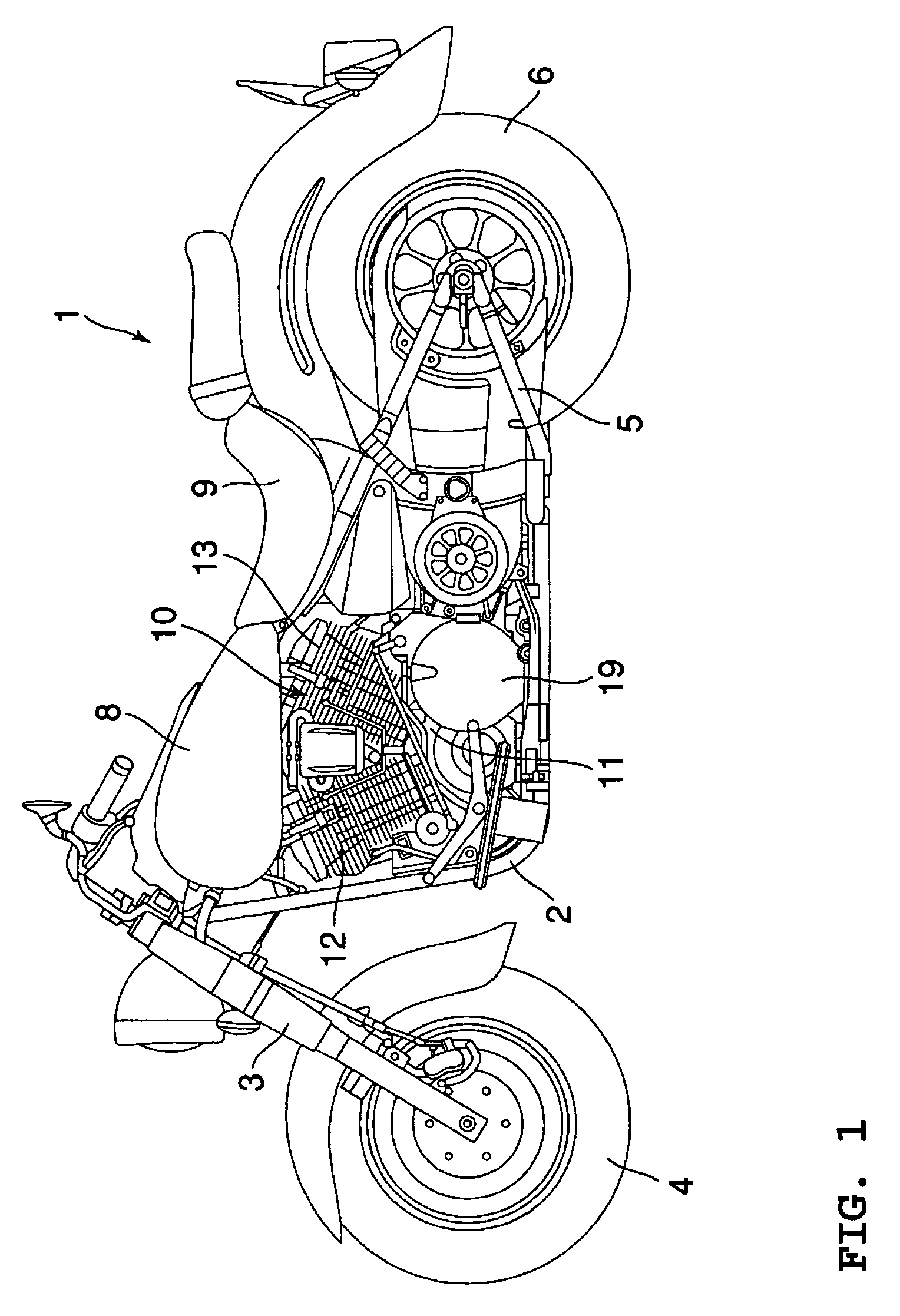
[0035]FIG. 1 is a drawing showing a motorcycle 1 relating to an embodiment of the present invention. The motorcycle 1 includes a cradle frame 2. A front fork 3 is attached to the front end of the frame 2. The front fork 3 supports the front wheel 4. A rear swing arm 5 is attached to the roar end of this frame 2. This rear spring arm 5 supports the rear wheel 6.

[0036]The frame 2 supports a fuel tank 8, a seat 9 and a dry-sump air-cooled four-stroke V-type two-cylinder engine 10. This engine 10 is installed, between the front wheel 4 and rear wheel 6 as well as below the fuel tank 8.

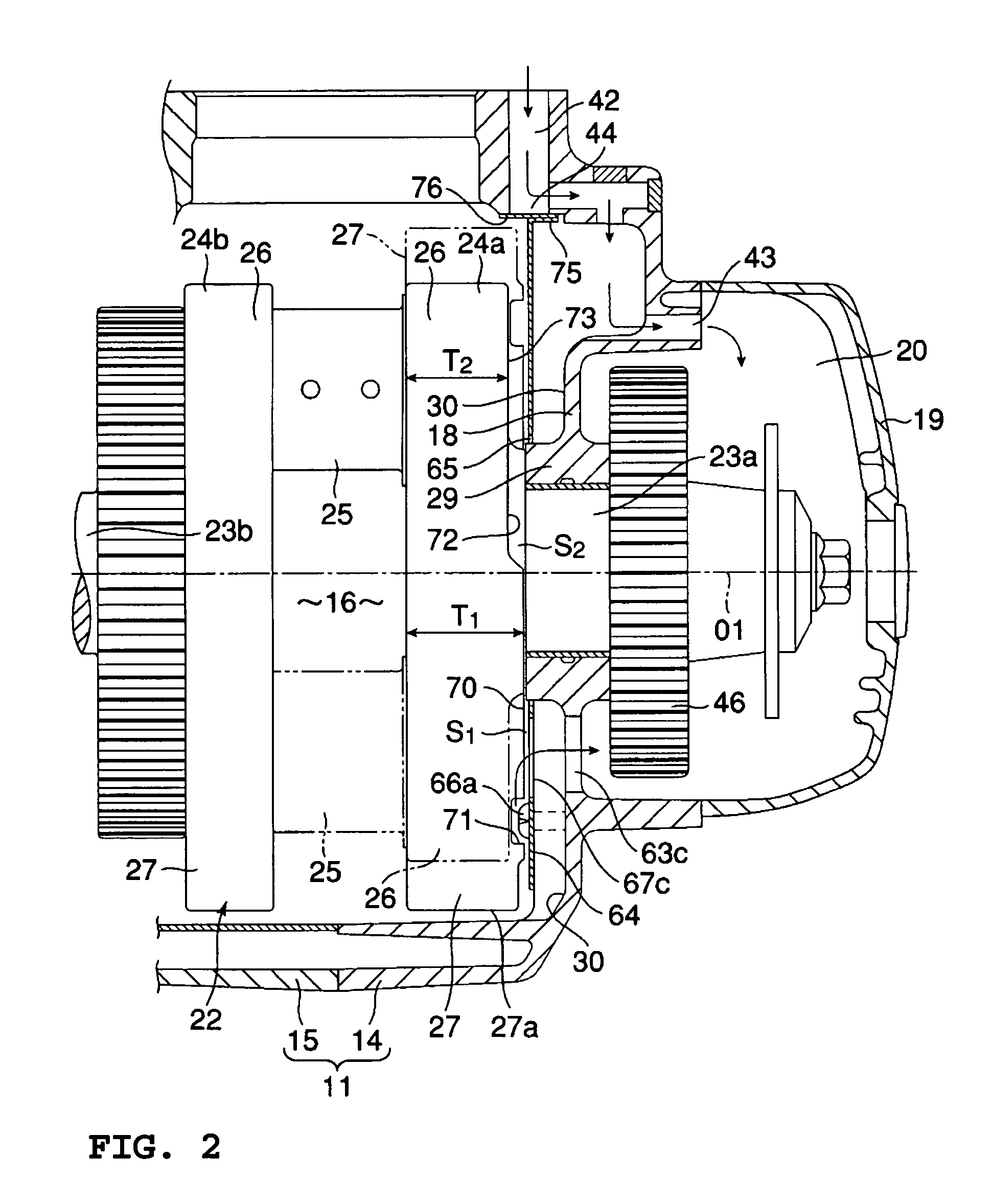
[0037]The engine 10 includes a crankcase 11, a front cylinder 12 and a rear cylinder 13. The crankcase 11, as shown in FIG. 2, is separated into a left case 14 and a right case 15. A crank chamber 16 and a transmission chamber 17 are formed between the left case 14 and the right case 15. The crank cham...


PUM


Abstract

A lubrication device for a dry-sump, four-stroke engine includes a crankcase having a divider wall interposed between a crank chamber and a separate adjoining chamber. A crankshaft is housed in the crank chamber and is driven by reciprocating movement of pistons. A crank web faces the divider wall, which has a through hole for connecting the crank chamber with the separate chamber, and is opened by the crank web when the piston moves from a top dead center position toward a bottom dead center position, and is closed when the piston moves from the bottom dead center toward the top dead center position. A return hole connects the crank chamber and the separate chamber, for returning lubricant oil that flowed through the through hole into the separate chamber from the crank chamber, back to the crank chamber by utilizing pressure fluctuations within the crank chamber.

Description

BACKGROUND OF THE INVENTION[0001]1. Field of the Invention[0002]The present invention relates to a lubrication device for a dry-sump, four-stroke engine formed with through holes for absorbing a fluctuating pressure within a crank chamber, which is installed for example in a wall separating a clutch chamber and the crank chamber, and relates in particular to a mechanism for accelerating the return of lubricant oil to the crank chamber during a piston's movement from a bottom dead center position to a top dead center position.[0003]2. Description of Related Art[0004]In dry-sump, four-cycle engines not possessing an effective oil pan in the bottom of the crank chamber, when the diameter of a crank web is enlarged to increase the inertial mass of a crankshaft, the outer circumferential surface of the crank web nears the bottom of the crank chamber.[0005]The increase in pressure inside the crank chamber while the piston falls downward from the top dead center to the bottom dead center i...

Claims


Application Information

Patent Timeline
Patent Type & Authority Patents(United States)
IPC IPC(8): F01M1/00F01M1/06F01M1/02F01M1/04F01M1/12F01M11/00F02B61/02F02B75/22
CPCF01M1/12F01M2001/126F02B61/02F02B75/22
Inventor TAKEUCHI, YOSHIHIKO
Owner YAMAHA MOTOR CO LTD
Why Eureka
Try Eureka