Stapling device

Inactive Publication Date: 2006-03-21
CHANG CHUN YUAN
View PDF18 Cites 14 Cited by
  • Summary
  • Abstract
  • Description
  • Claims
  • Application Information

AI Technical Summary

Benefits of technology

[0009]The primary objective of the present invention is to provide a stapling device including a staple magazine

Problems solved by technology

However, it will be difficult for the users to open the driving member, and then to change the staples.
However,

Method used


Image

  • Stapling device
  • Stapling device
  • Stapling device

Examples


Embodiment Construction

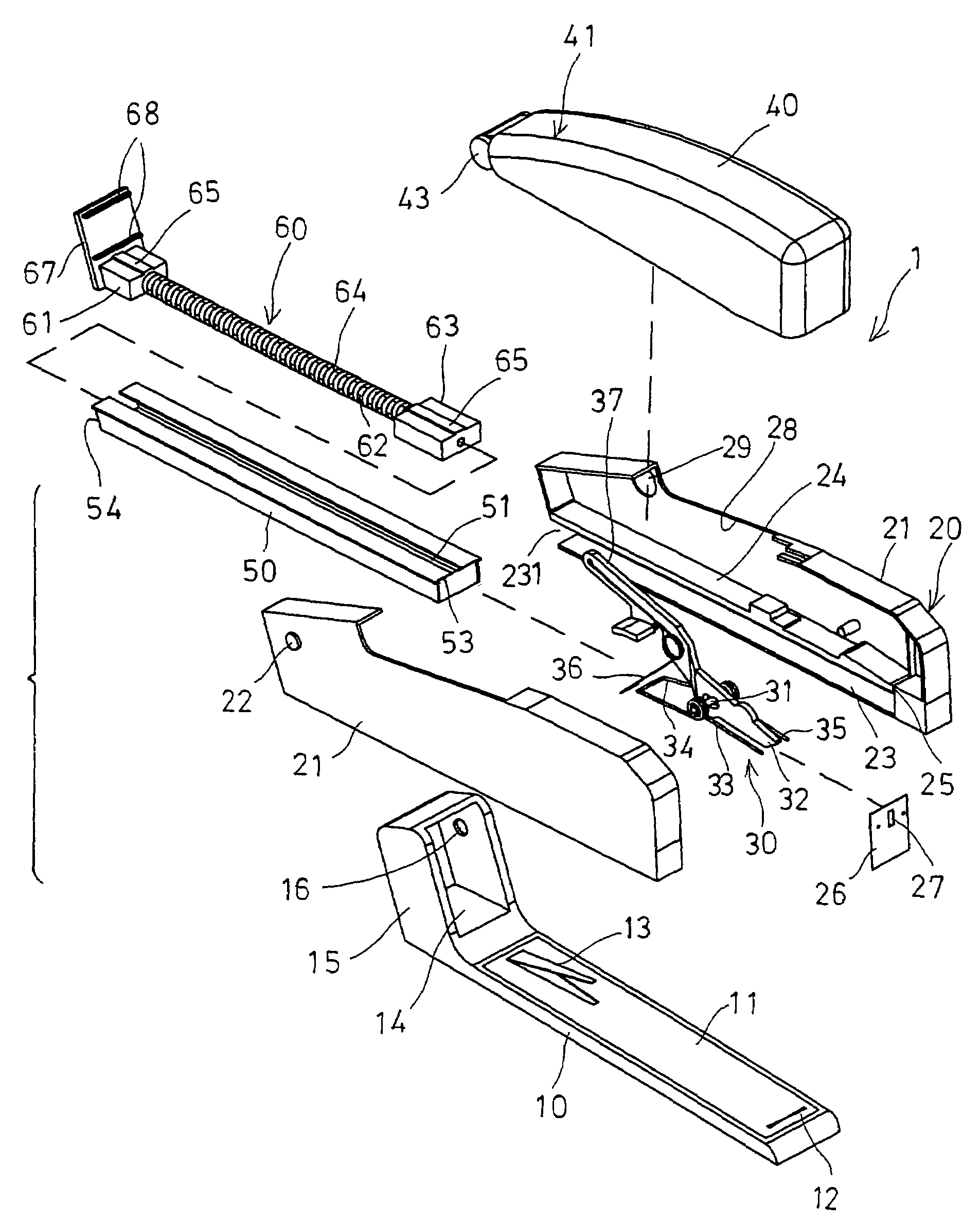
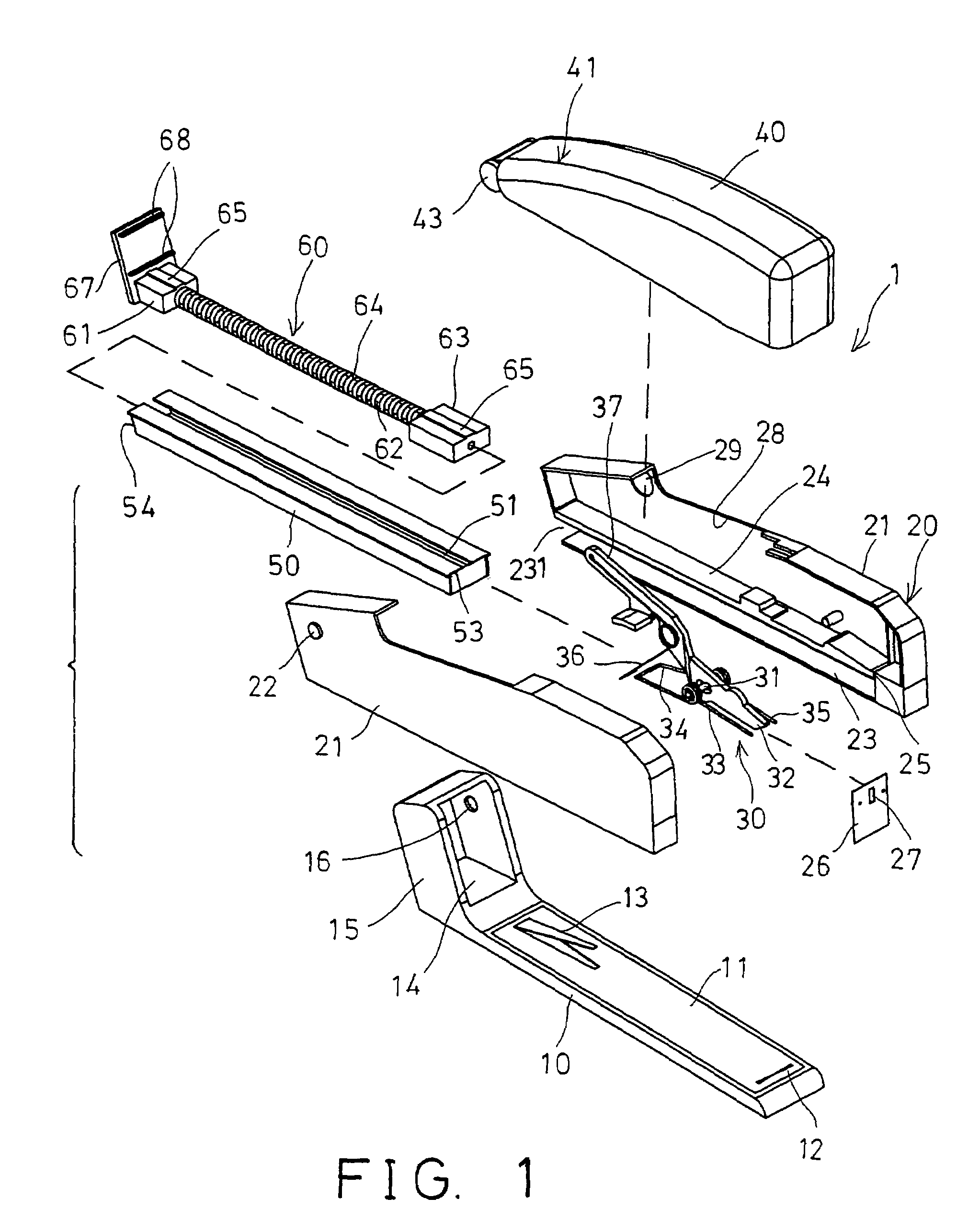
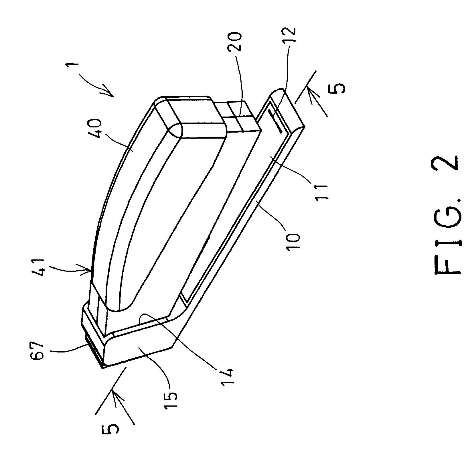
[0024]Referring to the drawings, and initially to FIGS. 1–5, a stapling device 1 in accordance with the present invention comprises a base member 10, an anvil plate 11 disposed in the upper portion of the base member 10 and having one or more inward staple guide depressions 12 formed in such as a front portion thereof, and having a spring arm 13 extended upward from the rear portion thereof. The base member 10 includes a space 14 formed in the rear portion thereof, and defined between two side panels 15 each having a cavity 16 formed therein.

[0025]A housing 20 may include such as two housing members 21 secured together by fasteners, latches (not shown), adhesive materials, or by welding processes, or the like, and includes an axle 22 provided on one end thereof for engaging into the cavities 16 of the base member 10, and for rotatably securing the housing 20 to the base member 10, and for allowing the housing 20 to be rotated relative to the base member 10. For example, the axle 22 ...


PUM


Abstract

A stapling device includes a housing pivotally attached to a base member and having a channel formed by a partition, a staple drive plate slidably received in the housing, a staple magazine slidably engageable in the channel of the housing and having a front staple drive space. A staple feeder is engaged into the staple magazine and includes a spring-biased pusher for forcing staples forwardly toward the staple drive space of the staple magazine, and for allowing the staples to be driven by the staple drive plate, and an actuating device for actuating the staple drive plate to drive the staples. The staple magazine may be easily disengaged from the housing from a rear inlet of the housing.

Description

BACKGROUND OF THE INVENTION[0001]1. Field of the Invention[0002]The present invention relates to a stapling device, and more particularly to a stapling device having a staple magazine openable rearwardly from a stapler housing, to allow staples to be easily and quickly changed with new staples.[0003]2. Description of the Prior Art[0004]Various kinds of typical stapling devices have been developed and comprise a base member having an anvil plate, a staple magazine member and a driving member provided with a staple drive plate. A staple guide member and a staple feeder are coupled to the driving member, to feed the staples toward the driving member, and to allow the staples to be suitably driven or hammered by the driving member.[0005]For example, U.S. Pat. No. 4,496,091 to Yasuda discloses one of the typical stapling devices also comprising a staple guide member and a staple feeder to feed the staples toward a driving member. The driving member should be opened or rotated relative to...

Claims


Application Information

Patent Timeline
IPC IPC(8): B25C1/00B25C5/06
CPCB25C5/0242
Inventor CHANG, CHUN YUAN
Owner CHANG CHUN YUAN
Why Eureka
Try Eureka