Liquid reservoir apparatus

a technology of liquid reservoir and liquid reservoir, which is applied in the field of liquid reservoir apparatus, can solve the problems of increasing the number of components, increasing the manufacturing cost, and difficulty in managing the generation of negative pressure of about several hundred pa, and achieves the effects of ensuring chemical stability against liquid, low ink channel resistance, and low cos

Inactive Publication Date: 2006-03-21
CANON KK
View PDF18 Cites 6 Cited by
  • Summary
  • Abstract
  • Description
  • Claims
  • Application Information

AI Technical Summary

Benefits of technology

[0016]It is, therefore, an object of the present invention to provide a liquid reservoir apparatus which can ensure a chemical stability against a liquid with an arrangement that can be manufactured at a comparatively low cost, can generate a negative pressure with a low ink channel resistance regardless of a difference in posture of the liquid tank, and can supply the liquid stably.

Problems solved by technology

This is a significant issue in designing the inkjet printer.
As in these ink reservoir apparatuses, when the internal pressure of the soft, flexible bag 221 is to be controlled with some mechanism, generally, the number of components increases and the manufacturing cost increases.
It is also technically difficult to manage generation of a negative pressure of about several hundred Pa.
Furthermore, when the bag is thin, it has poor hermeticity.
When ink is stored in the thin bag over a long period of time, the external air may enter the bag to expand it, or the ink in the bag may evaporate.
Therefore, when a mechanism that generates a negative pressure is to be added to an ink reservoir apparatus using a bag while ensuring the reliability, many problems must be solved.
A sponge manufactured by a general sponge manufacturing method, however, does not have a sufficiently high density, and must be used after it is compressed to a certain degree.
A commercially available sponge is often made of a urethane resin and has a comparatively low chemical stability.
Then, a large amount of product produced from the ink often adversely affects a portion in the vicinity of the nozzle.
Various types of ink are used to expand the use of the ink-jet printer, but the chemical stability of the sponge poses an issue.
Accordingly, the composition of the ink must often be unavoidably changed to improve the chemical stability, while the physical characteristics are degraded.
This phenomenon is a critical problem.

Method used


Image

  • Liquid reservoir apparatus
  • Liquid reservoir apparatus
  • Liquid reservoir apparatus

Examples


first embodiment

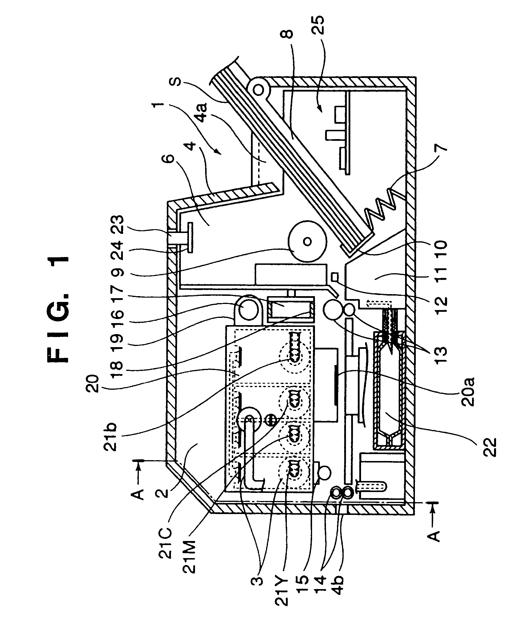
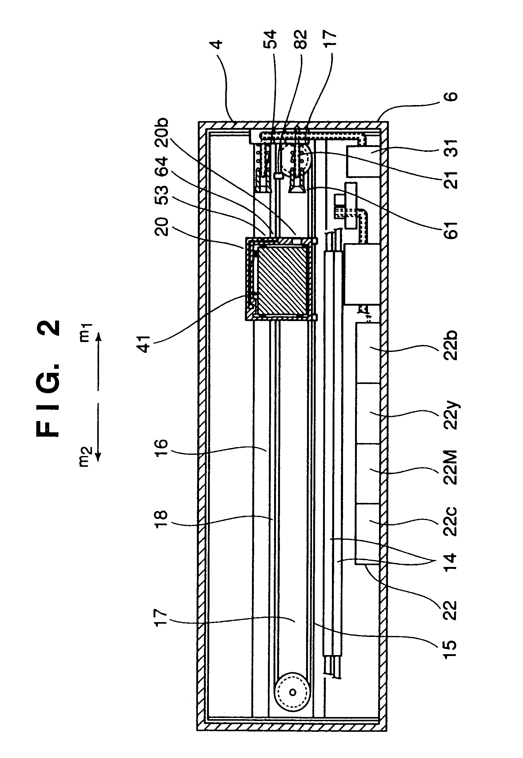
[0056]FIGS. 1 and 2 are sectional views showing the schematic structure of an inkjet printer according to this embodiment. The inkjet printer of this embodiment employs a serial scan scheme with which the inkjet head moves in the main scanning direction.

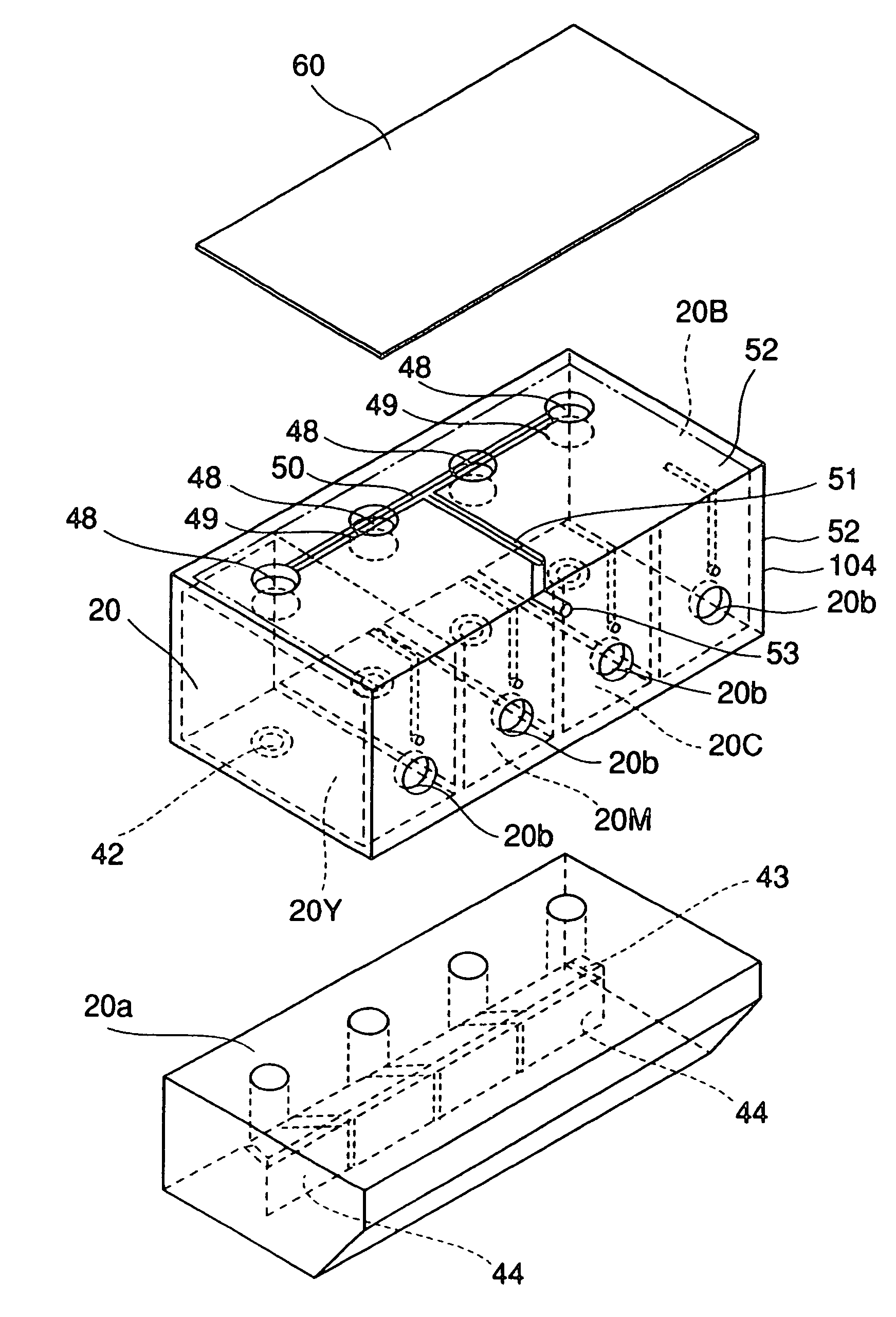
[0057]As shown in FIG. 1, the inkjet printer (to be simply referred to as a printer hereinafter) has a feed section 1 which feeds a printing medium S, a printing section 2 which discharges ink onto the printing medium S to print a character, an image, or the like, an ink replenishing section 3 which replenishes the ink, and a cover 4 which forms an outer housing.

[0058]The cover 4 has an insert port 4a through which the printing medium S is inserted and a discharge port 4b through which the printing medium S is discharged. An image or the like is printed on the printing medium S inserted from the insert port 4a with the printing section 2, and the printing medium S is discharged from the discharge port 4b.

[0059]The feed section 1 has...

second embodiment

[0125]FIGS. 14A, 14B, and 14C show a reservoir ink tank according to the second embodiment which employs the structure of the present invention. In the reservoir ink tank of this embodiment, the arrangements and functions of the respective portions are the same as those of the reservoir ink tank of the first embodiment, but devices are added to this reservoir ink tank to further improve the reliability. In the reservoir ink tank of this embodiment, for the sake of descriptive convenience, the same members as those of the reservoir ink tank of the first embodiment described above are denoted by the same reference numerals, and a detailed description thereof will be omitted.

[0126]As shown in FIGS. 14A, 14B, and 14C, an ink reservoir 166 has a taper shape in which its gap size d gradually increases as the gap is more distant from the ink supply port 165.

[0127]FIGS. 15A, 15B, and 15C are views for explaining the shapes of thin bodies 164 used for forming the ink reservoir 166 having the...

third embodiment

[0131]Finally, an ink reservoir tank according to the third embodiment will be described with reference to the accompanying drawings. FIGS. 17A and 17B show an ink reservoir tank according to the third embodiment. In the reservoir ink tank of this embodiment, for the sake of descriptive convenience, the same members as those of the reservoir ink tank of the first embodiment described above are denoted by the same reference numerals, and a description thereof will be omitted.

[0132]As shown in FIGS. 17A and 17B, according to this reservoir ink tank, thin bodies 181 each having a substantially wave shape are disposed in a housing.

[0133]Each thin body 181 is formed of a plate material to have the substantially wave shape, as shown in FIG. 18, and is arranged to form a wave shape in the horizontal direction. The thin bodies 181 are arranged such that the recesses and projections of their wave shape coincide with each other, so that a wave shaped ink reservoir is formed.

[0134]In this mann...


PUM


Abstract

An ink reservoir (166) has a plurality of thin bodies (164) provided in a housing (161) at gaps from each other. Ink in the housing (161) is held by a capillary force generated by the thin bodies (164). An ink guide portion (167) which is set at a gap between one end of the liquid ink (166) and an inner wall of the housing (161) is provided so that a capillary force in the vicinity of an ink supply port (165) is larger than that of the liquid reservoir (166).

Description

FIELD OF THE INVENTION[0001]The present invention relates to a liquid reservoir apparatus provided to a printer that prints by discharging ink onto, e.g., a printing sheet and, more particularly, to a liquid reservoir apparatus which uses a gas / liquid separating member for supplying a liquid such as ink.BACKGROUND OF THE INVENTION[0002]Conventionally, as an inkjet printer, one having an inkjet printhead which discharges ink droplets, a main tank which stores ink to be supplied to the ink-jet printhead, and a subtank which holds the ink supplied from the main tank is known.[0003]In an inkjet printer of this type, many ink supply mechanisms which supply ink to the ink-jet printheads have been proposed and put into practical use. To supply the ink to the inkjet printhead, the capillary force of the nozzle itself of the ink-jet printhead is utilized, and accordingly no external force of a pump or the like is usually required. Therefore, a mechanism which supplies ink with a pressure fro...

Claims


Application Information

Patent Timeline
Patent Type & Authority Patents(United States)
IPC IPC(8): B41J2/175
CPCB41J2/17556
Inventor NETSU, HIROSHISHIMODA, JUNJIUJITA, TOSHIHIKOOKAMOTO, HIDEAKI
Owner CANON KK
Why Eureka
Try Eureka