Method and apparatus for splicing optical fibres

a technology of optical fibres and splicing devices, applied in the field of splicing optical fibres, can solve the problems of damage to the fibre end face, loss of advantageous effects of angled cleaving, and high cost and time consumption

Inactive Publication Date: 2006-03-21
TYCO ELECTRONICS RAYCHEM BVBA
View PDF19 Cites 28 Cited by
  • Summary
  • Abstract
  • Description
  • Claims
  • Application Information

AI Technical Summary

Benefits of technology

[0006]Although fibres having such an angled end face potentially perform very well, a problem arises when they are to be spliced. For the angled end faces to abut properly, leaving virtually no gap, the end faces have to be parallel. This requires the fibres to have a very specific keyed orientation when they are accommodated in a splice body. In existing splicing methods, the relative orientation of the fibres is arbitrary. Of course it is possible to experimentally determine the proper orientation of the fibres by accommodating them in a splice and then measuring the reflection losses at various orientations. This is, however, both expensive and time consuming and may cause the fibre end faces to be damaged. Alternatively optical gel (index matching gel) may be used to reduce the adverse effects of an improper relative orientation of the fibre end faces but it has been found that the advantageous effects of the angled cleaving may still be lost.
[0007]It is therefore an object of the present invention to overcome the above-mentioned and other disadvantages of the Prior Art and to provide a method of splicing optical fibres which fully utilises the advantages of angled cleaving.
[0008]It is a further object of the present invention to provide a method of splicing optical fibres which is both practical and economical.
[0009]It is another object of the present invention to provide apparatus for implementing the inventive method.
[0010]Accordingly, the present invention provides a method of splicing optical fibres, the method comprising the steps of affixing a first fibre to a first keying element having a particular radial orientation, inserting the keying element in a support which receives the keying element only in a specific radial orientation, cleaving the fibre affixed to the inserted keying element at a predetermined angle (α) relative to the support to form an angled fibre end face, removing the keying element from the support, inserting the keying element into a splicing body which receives the keying element only in a specific radial orientation such that the angled fibre end face has a predictable radial orientation with respect to the splice body, and repeating the above steps for a second fibre and a second keying element, whereby the first angled fibre end face and the second angled fibre end face abut in a substantially parallel orientation.
[0011]By cleaving the fibres at a specific radial orientation and accommodating them again at a specific radial orientation, a predictable relative orientation of the abutting fibres is achieved. In this way, a substantially perfect parallel abutment of the fibre end faces can be achieved.

Problems solved by technology

Although fibres having such an angled end face potentially perform very well, a problem arises when they are to be spliced.
This is, however, both expensive and time consuming and may cause the fibre end faces to be damaged.
Alternatively optical gel (index matching gel) may be used to reduce the adverse effects of an improper relative orientation of the fibre end faces but it has been found that the advantageous effects of the angled cleaving may still be lost.

Method used


Image

  • Method and apparatus for splicing optical fibres
  • Method and apparatus for splicing optical fibres
  • Method and apparatus for splicing optical fibres

Examples


Embodiment Construction

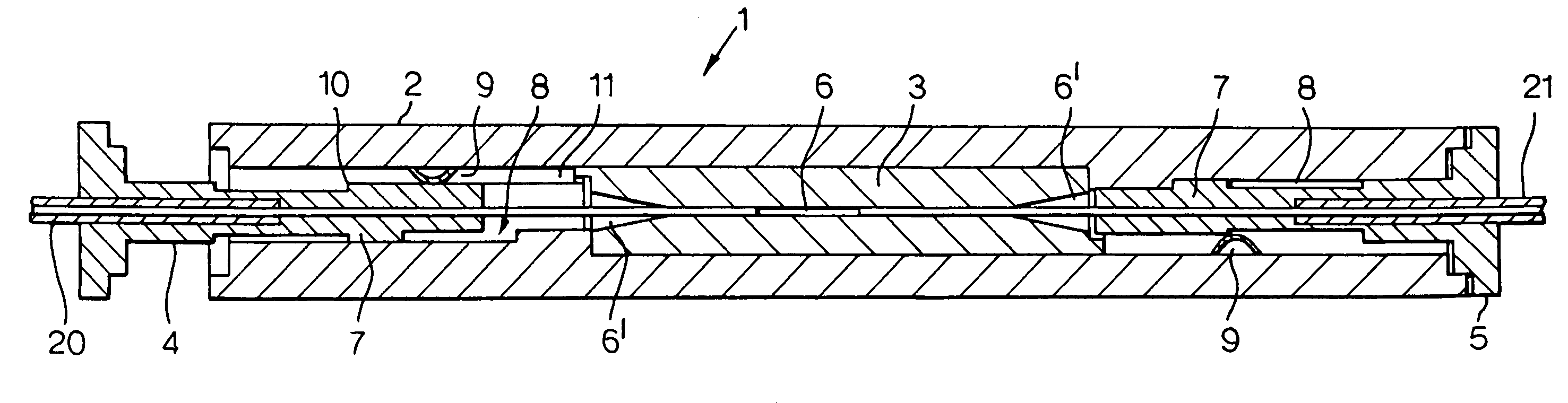
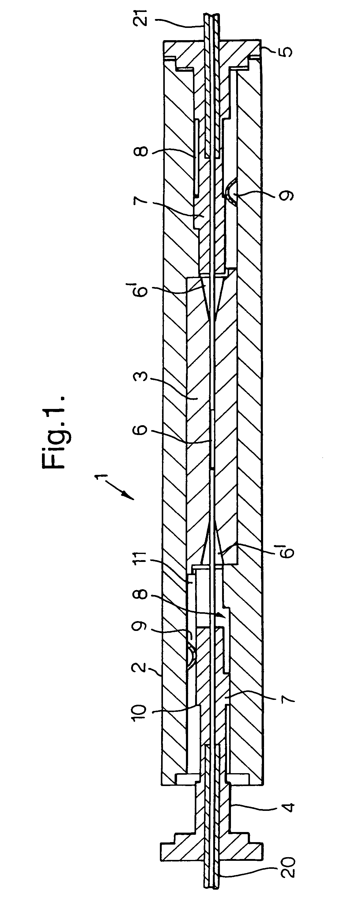
[0027]The mechanical splice 1 shown merely by way of non-limiting example in FIG. 1 comprises a substantially tubular body 2, an alignment member 3 and two keying elements 4 and 5. Optical fibres 20, 21 are accommodated in the keying elements 4, 5 respectively. As shown in FIG. 1, the cladding has been removed from the end portions of the fibres. The fibre ends meet in the alignment member 3 which is provided with a V-shaped groove 6 for accommodating and aligning the fibre ends. The groove has widened sections 6′ at the ends of the alignment member 3 which allow the fibres to buckle in those areas so as to maintain a compressive force on the abutting fibre end faces.

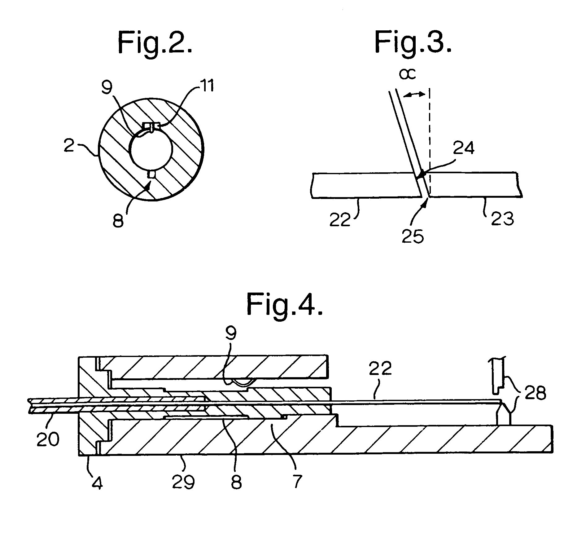
[0028]In accordance with the present invention, the splicing device 1 is provided with a mechanism for defining and maintaining the angular orientation of the optical fibres. This mechanism comprises keying ridges or protrusions 7 provided on the keying elements 4, 5, which protrusions can be accommodated in keying slot...


PUM


Abstract

A method of splicing optical fibers includes affixing a first fiber to a first keying element having a particular radial orientation, inserting the keying element in a support which receives the keying element only in a specific radial orientation, cleaving the fiber affixed to the inserted keying element at a predetermined angle (α) relative to the support to form an angled fiber end face, removing the keying element from the support, inserting the keying element into a splicing body which receives the keying element only in a specific radial orientation such that the angled fiber end face has a predictable radial orientation with respect to the splice body, and repeating the above operations for a second fiber and a second keying element, whereby the first angled fiber end face and the second angled fiber end face abut in a substantially parallel orientation.

Description

RELATED APPLICATIONS[0001]The present application is a National Phase application of PCT / GB02 / 04163 filed on Sep. 11, 2002 and published in English, which claims priority from Application GB 0123830.2 filed on Oct. 4, 2001.BACKGROUND OF THE INVENTION[0002]The present invention relates to method and apparatus for splicing optical fibres. More in particular, the present invention relates to a method of splicing optical fibres in which the ends of the fibres are cut at a non-perpendicular angle.[0003]Optical fibres can be interconnected or “spliced” in several ways. Fusion splicing involves heating the ends of the fibres to be spliced in order to produce a continuous transition. Mechanical splicing involves abutting the fibre ends in a suitable support or “splice”. As mechanical splicing does not require any heating, it is often preferred for splicing in the field. The mechanical splice device needs to be carefully designed to achieve a proper alignment of the fibre ends. Examples of s...

Claims


Application Information

Patent Timeline
Patent Type & Authority Patents(United States)
IPC IPC(8): G02B6/255G02B1/00G02B6/38
CPCG02B6/3809G02B6/3822G02B6/38
Inventor WATTE, JANDAEMS, DANIELELENBAAS, JACCOHULTERMANS, TWANBOLHAAR, TON
Owner TYCO ELECTRONICS RAYCHEM BVBA
Why Eureka
Try Eureka