Turbine element

a turbine element and turbine technology, applied in the direction of liquid fuel engines, foundry patterns, moulding apparatus, etc., can solve the problem of limited efficiency of turbine elements, and achieve the effect of reducing the thermal performance of turbine elements

Active Publication Date: 2006-03-21
RTX CORP
View PDF7 Cites 110 Cited by
  • Summary
  • Abstract
  • Description
  • Claims
  • Application Information

AI Technical Summary

Benefits of technology

[0008]In various implementations, the posts may have dimensions along the slot no greater than 0.10 inch. The second end may be a free tip. The posts may include a leading group of posts, a first metering row of posts trailing the leading group, a second metering row of posts trailing the first metering row, and at least one intervening group between the first and second metering rows. The first metering row may have a restriction factor greater than that of the leading group. The second metering row may have a restriction factor greater than that of the leading group. The intervening group may have a restriction factor less than the restriction factors of the first and second metering rows. The posts may include a trailing array of posts spaced ahead of an outlet of the slot. The blade may consist essentially of a nickel alloy. The exact trailing edge of the airfoil may fall along an outlet of the slot. The posts may be arranged with a leading group of a number of rows of essentially circular posts, a trailing row of essentially circular posts, and intervening rows of posts having sections elongate in the direction of their associated rows. The posts may have dimensions along the slot no greater than 0.10 inch.
[0009]Another aspect of the invention is a turbine element-forming core assembly including a ceramic element and a refractory metal sheet. The ceramic element has portions for at least partially defining associated legs of a conduit network within the turbine element. The refractory metal sheet is secured to the ceramic element positioned extending aft of a trailing one of the portions. The sheet has apertures extending between opposed first and second surfaces for forming associated posts between pressure and suction side portions of an airfoil of the turbine element.

Problems solved by technology

Efficiency is limited by turbine element thermal performance.

Method used


Image

  • Turbine element
  • Turbine element
  • Turbine element

Examples


Embodiment Construction

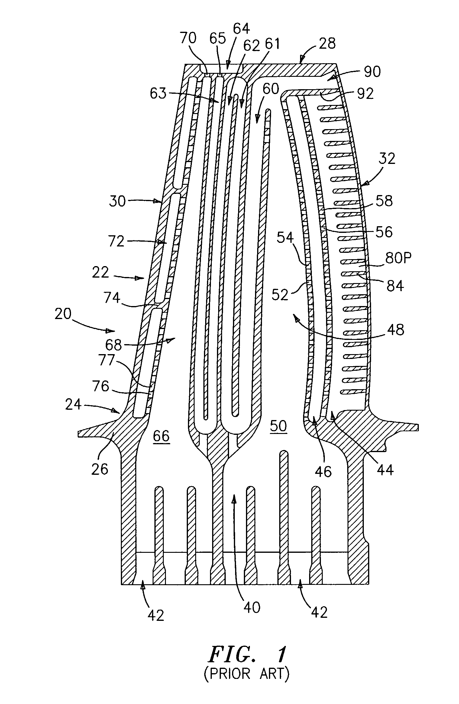
[0020]FIG. 1 shows a prior turbine blade 20 having an airfoil 22 extending along a length from a proximal root 24 at an inboard platform 26 to a distal end 28 defining a blade tip. A number of such blades may be assembled side by side with their respective platforms forming an inboard ring bounding an inboard portion of a flow path. In an exemplary embodiment, the blade is unitarily formed of a metal alloy.

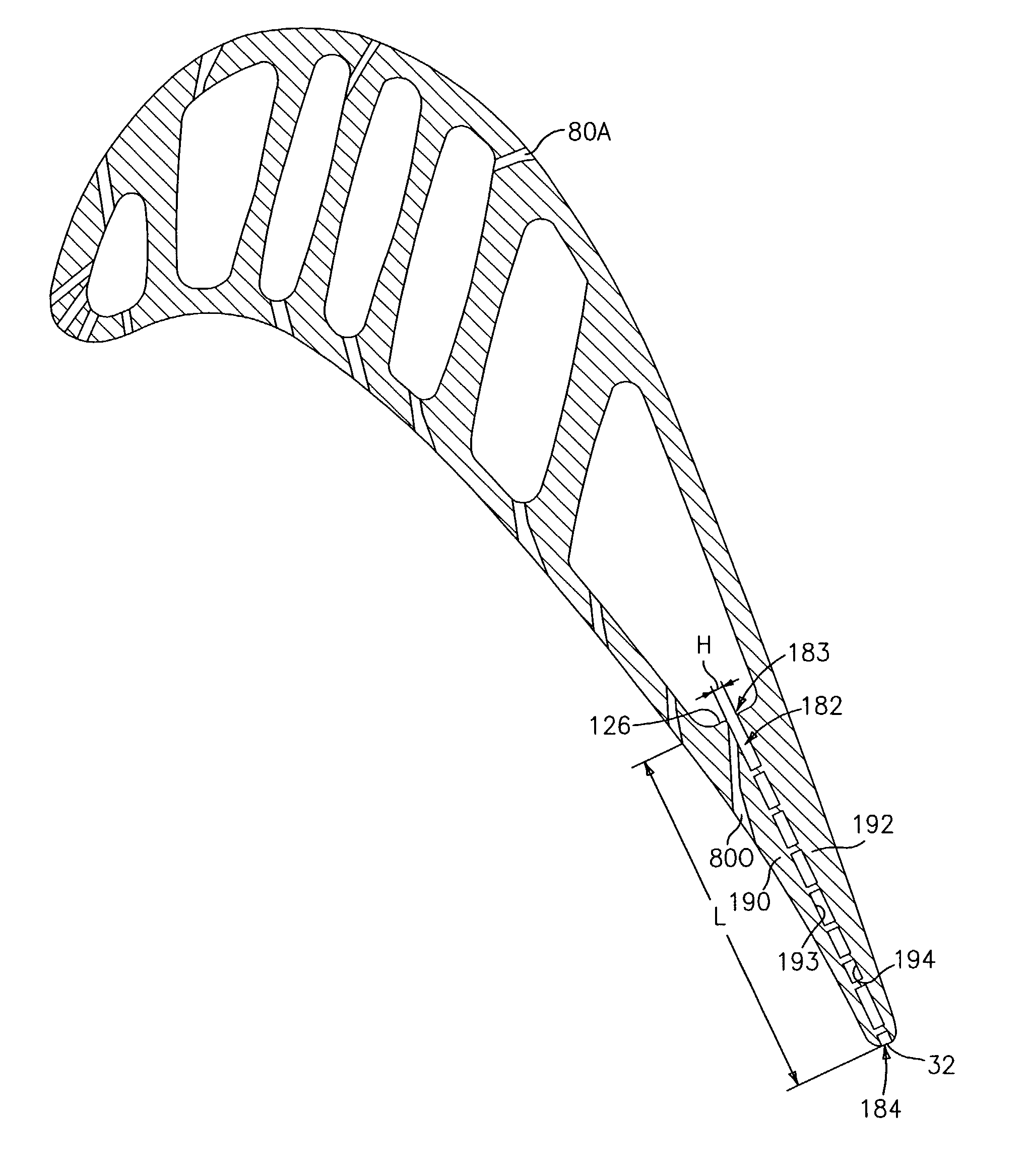
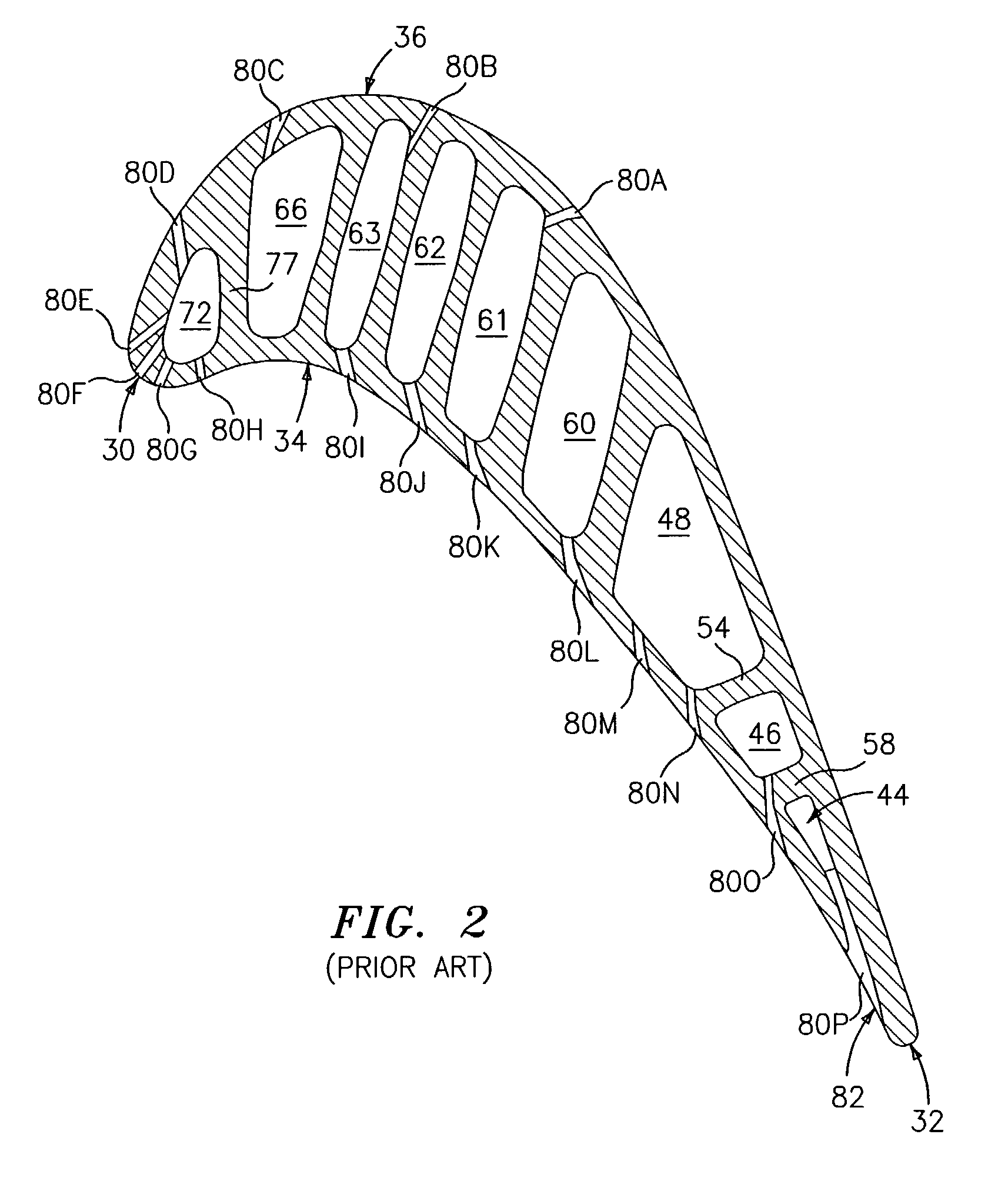
[0021]The airfoil extends from a leading edge 30 to a trailing edge 32. The leading and trailing edges separate pressure and suction sides or surfaces 34 and 36 (FIG. 2). For cooling the airfoil, the airfoil is provided with a cooling passageway network 40 (FIG. 1) coupled to ports 42 in the platform. The exemplary passageway network includes a series of cavities extending generally lengthwise along the airfoil. An aftmost cavity is identified as a trailing edge cavity 44 extending generally parallel to the trailing edge 32. A penultimate cavity 46 is located ahead of the trailing...


PUM

PropertyMeasurementUnit
heightaaaaaaaaaa
diameter D1aaaaaaaaaa

Abstract

A turbine element airfoil has a cooling passageway network with a slot extending from a trailing passageway toward the trailing edge. A number of discrete posts span the slot between pressure and suction sidewall portions.

Description

U.S. GOVERNMENT RIGHTS[0001]The government may have rights in this invention, pursuant to Contract Number F33615-02-C-2202, awarded by the United States Air Force, Wright Patterson Air Force Base.BACKGROUND OF THE INVENTION[0002](1) Field of the Invention[0003]This invention relates to gas turbine engines, and more particularly to cooled turbine elements (e.g., blades and vanes).[0004](2) Description of the Related Art[0005]Efficiency is limited by turbine element thermal performance. Air from the engine's compressor bypasses the combustor and cools the elements, allowing them to be exposed to temperatures well in excess of the melting point of the element's alloy substrate. The cooling bypass represents a loss and it is therefore desirable to use as little air as possible. Trailing edge cooling of the element's airfoil is particularly significant. Aerodynamically, it is desirable that the trailing edge portion be thin and have a low wedge angle to minimize shock losses.[0006]In one...

Claims


Application Information

Patent Timeline
Patent Type & Authority Patents(United States)
IPC IPC(8): B63H1/14B22C9/10B23P15/04F01D5/18F02C7/00
CPCB22C9/103F01D5/186F01D5/187F05D2260/22141F05D2230/21F05D2260/2212A61H7/004A61H39/04A61H2201/0134A61H2205/081A61H2201/1215
Inventor CUNHA, FRANK J.DAHMER, MATTHEW T.
Owner RTX CORP
Why Eureka
Try Eureka