Electric motor

a brushless, electric motor technology, applied in the direction of magnetical circuit shape/form/construction, instruments, horology, etc., can solve the problem of constructing such motors at the lowest possible cost, and achieve the effect of low cos

Inactive Publication Date: 2006-03-21
MINEBEA CO LTD
View PDF8 Cites 40 Cited by
  • Summary
  • Abstract
  • Description
  • Claims
  • Application Information

AI Technical Summary

Benefits of technology

[0035]A solution which can be produced at particularly low cost further provides that both stator units are of identical construction so that they can be constructed from identical parts.
[0036]Moreover, to clearly establish the rotational direction of the electric motor according to the invention, it is a particular advantage if holding positions of the rotor units determined by the magnetic effect, i.e. attraction, relative to the respective stator units are rotationally displaced in relation to each other by half a pole space.

Problems solved by technology

Such electric motors are known in the prior art, for which the problem is to construct such motors at the lowest possible cost and as simply as possible.

Method used


Image

  • Electric motor
  • Electric motor
  • Electric motor

Examples


Embodiment Construction

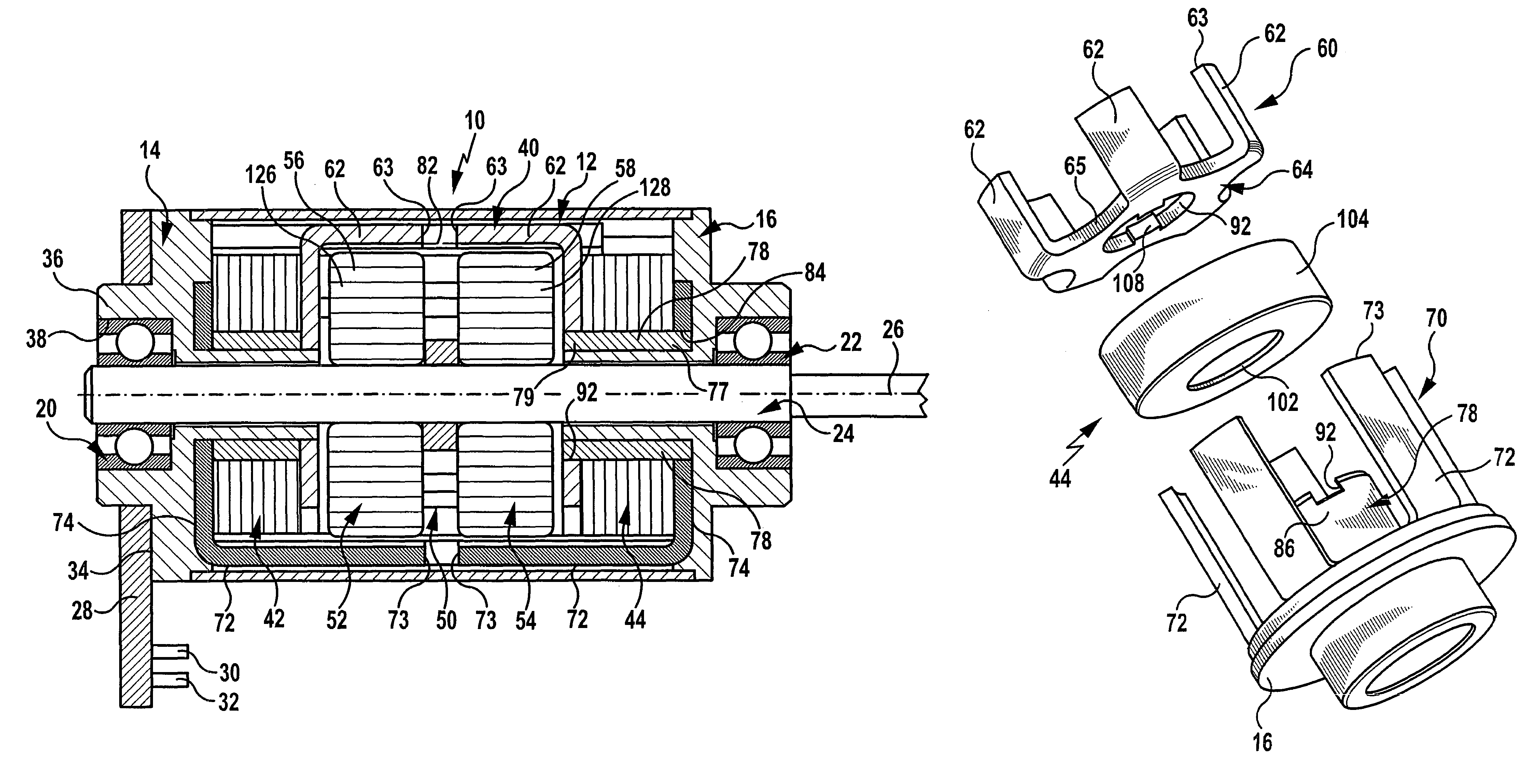
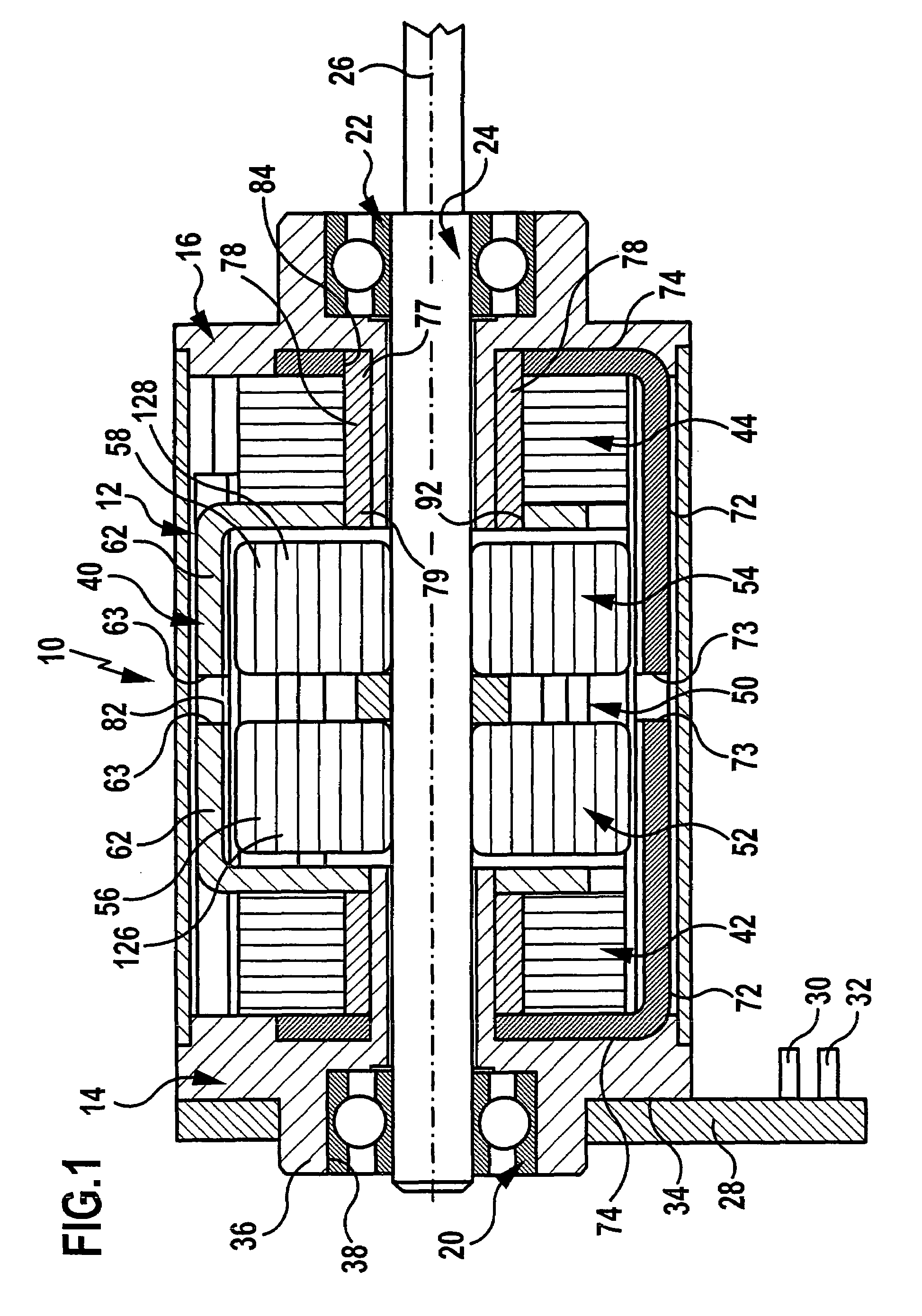
[0044]An embodiment of an electric motor according to the invention as illustrated in FIG. 1, preferably a stepper motor, includes a housing 10 with a housing sleeve 12 which extends between a first bearing support 14 and a second bearing support 16, both of which are fixedly connected to the housing sleeve 12.

[0045]In each of the bearing supports 14 and 16, a respective rotary bearing 20 and 22 is mounted, both preferably formed as ball bearings, by means of which a shaft 24 is mounted about an axis 26 to be rotatable with respect to the housing 10.

[0046]Moreover, the first bearing support 14 carries a connection board 28, on which electric terminals 30, 32 are disposed for connection of a power supply of the electric motor.

[0047]The connection board 28 is preferably then located on an outer surface 34 of the bearing support 14 and encloses a retaining ring 36 of the bearing support 14, which in turn forms a receptacle 38 for the rotary bearing 20.

[0048]Both a stator 40, formed by ...


PUM


Abstract

In order to construct a brushless electric motor comprising a housing, comprising a rotor and comprising a stator, each stator unit including pole shoes, formed as claw poles, as well as a coil positioned following the rotor in the direction of the rotor axis, by means of which the pole shoes can be magnetized, at the lowest possible cost and as simply as possible, it is proposed that the stator unit has two pole shoe elements of which a first pole shoe element has a first pole shoe carrier as well as first pole shoes formed integrally onto this carrier and of which a second pole shoe element has a second pole shoe carrier as well as the second pole shoes formed integrally onto this carrier and that a bearing support made of plastics is molded onto the second pole shoe carrier of the stator unit and is thereby secured to it.

Description

[0001]The present disclosure relates to the subject matter disclosed in European application No. 02 025 775.4 of Nov. 16, 2002, which is incorporated herein by reference in its entirety and for all purposes.BACKGROUND OF THE INVENTION[0002]The invention relates to a brushless electric motor, in particular a miniature motor, comprising a housing, comprising at least one rotor provided with magnetized regions and mounted rotatably about a rotor axis on bearing supports of the housing, and comprising a stator having at least one stator unit, each stator unit including a set of first pole shoes, formed as claw poles, and a set of second pole shoes, formed as claw poles, which are disposed around the rotor axis, as well as a coil positioned following the rotor in the direction of the rotor axis and with its windings arranged to encircle the rotor axis, by means of which the first and second pole shoes can be magnetized.[0003]Such electric motors are known in the prior art, for which the ...

Claims


Application Information

Patent Timeline
Patent Type & Authority Patents(United States)
IPC IPC(8): H02K37/14H02K1/14H02K1/02H02K5/15H02K21/14
CPCH02K21/145H02K5/15
Inventor BARRHO, GUENTHERWUERFEL, PETER
Owner MINEBEA CO LTD
Why Eureka
Try Eureka